Combined piston fluid motor and pump

Inactive Publication Date: 2005-06-09
SMITH CLYDE M
View PDF17 Cites 17 Cited by
  • Summary
  • Abstract
  • Description
  • Claims
  • Application Information

AI Technical Summary

Benefits of technology

[0009] The device of the present invention may have a utility for a variety of diverse applications without the need of electrical energy. Examples of such applications include, but are not limited to, proportioning, sampling, metering, flow detection, energy recovery, pressure intensification, and pumping. The device of the present invention may have advantages of cost, performance, simplicity and materials sufficient to displace devices in existing applications and enable potential new applications. Typically, two or more streams (liquid or gas) will be proportioned where one stream has a source pressure higher than its destination pressure and serves as an energy source to operate a reciprocating motor and the other streams have a source pressure lower than its destination pressure and use a pump powered by a motor to provide pressure and proportioning.
[0045] It is another object of the present invention to provide accurate, volumetric proportioning of two or more fluids.

Problems solved by technology

Fluid pumps driven by electric motors have a number of undesirable attributes.
For example, in some applications, fluid pumps using electric motors are undesirable for safety reasons.
For instance, when pumping solvents, acids, oils, and flammable liquids, it can be disadvantageous or even dangerous to operate high voltage or high current electric motors to drive the pumps.
As another example, fluid pumps using electrical motors do not easily start from a stalled condition and stop into a stalled condition.
Current fluid motors and pumps may have valve ports that limit fluid flow through the unit in a manner that results in pressure drop and turbulence through the motor.
When a powering fluid is saturated with a gas, for example, gas saturated carbonated water, too much pressure drop and turbulence through a fluid motor may cause the CO2 to bubble out of the solution, adversely affecting precision as a fluid powered proportioning pump for carbonated water and syrup.
In addition, internal valve leakage in the motor while shifting may adversely affect precision as a fluid powered proportioning pump.

Method used


Image

  • Combined piston fluid motor and pump
  • Combined piston fluid motor and pump
  • Combined piston fluid motor and pump

Examples


Embodiment Construction

[0061] Reference will now be made in detail to exemplary embodiments of the invention, an example of which is illustrated in the accompanying drawings. Wherever possible, the same reference numbers will be used throughout the drawings to refer to the same or like parts.

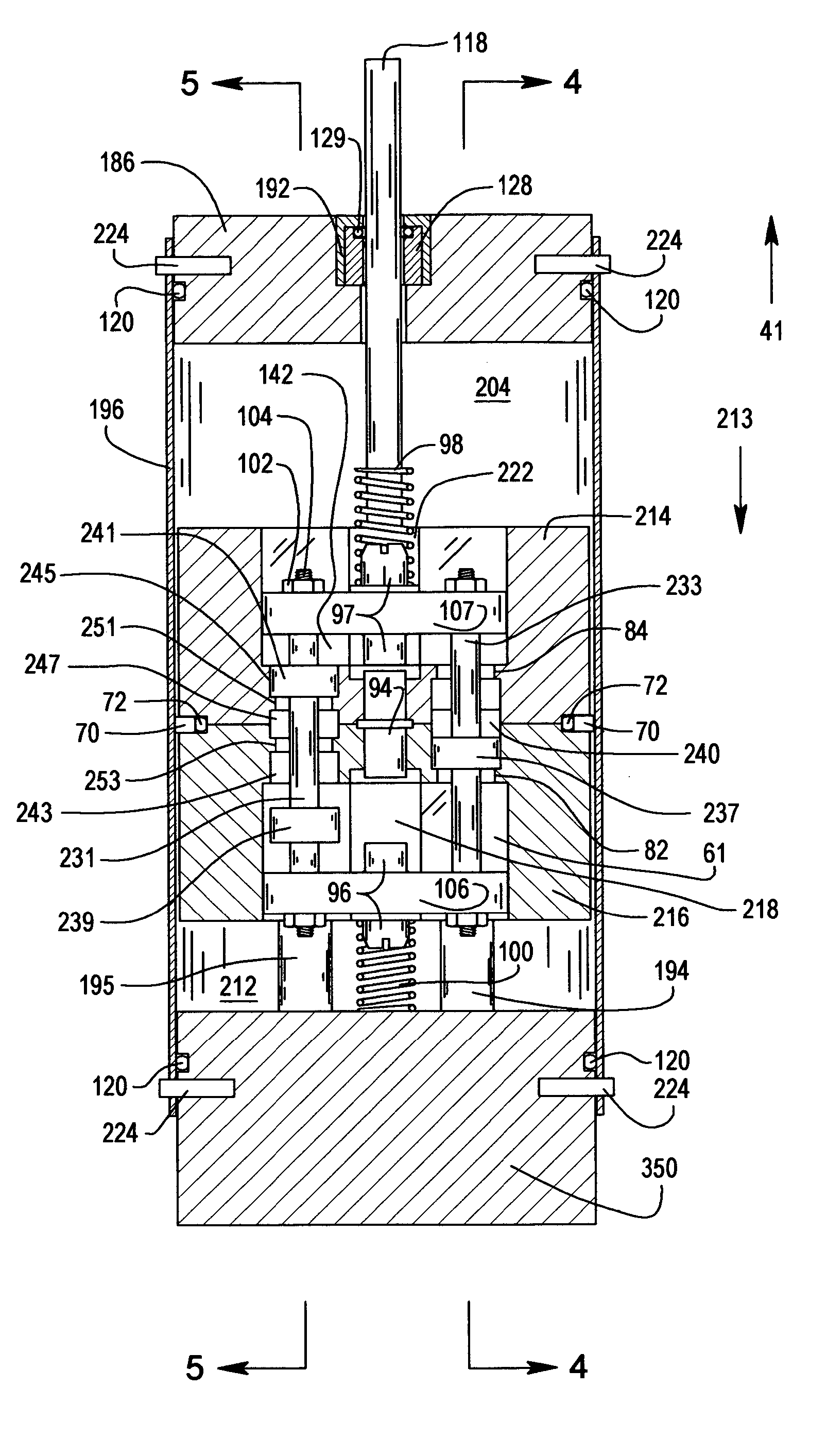
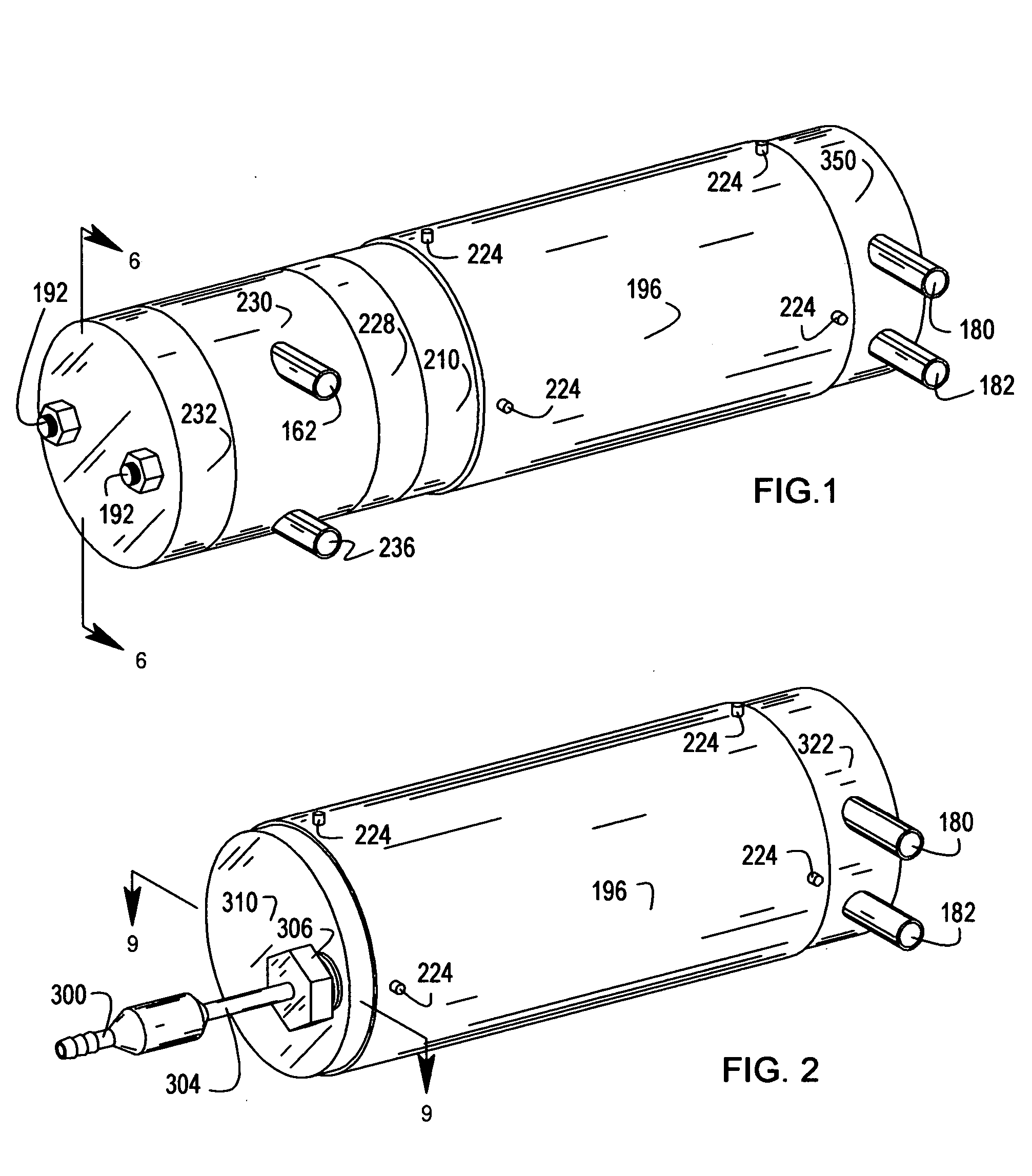
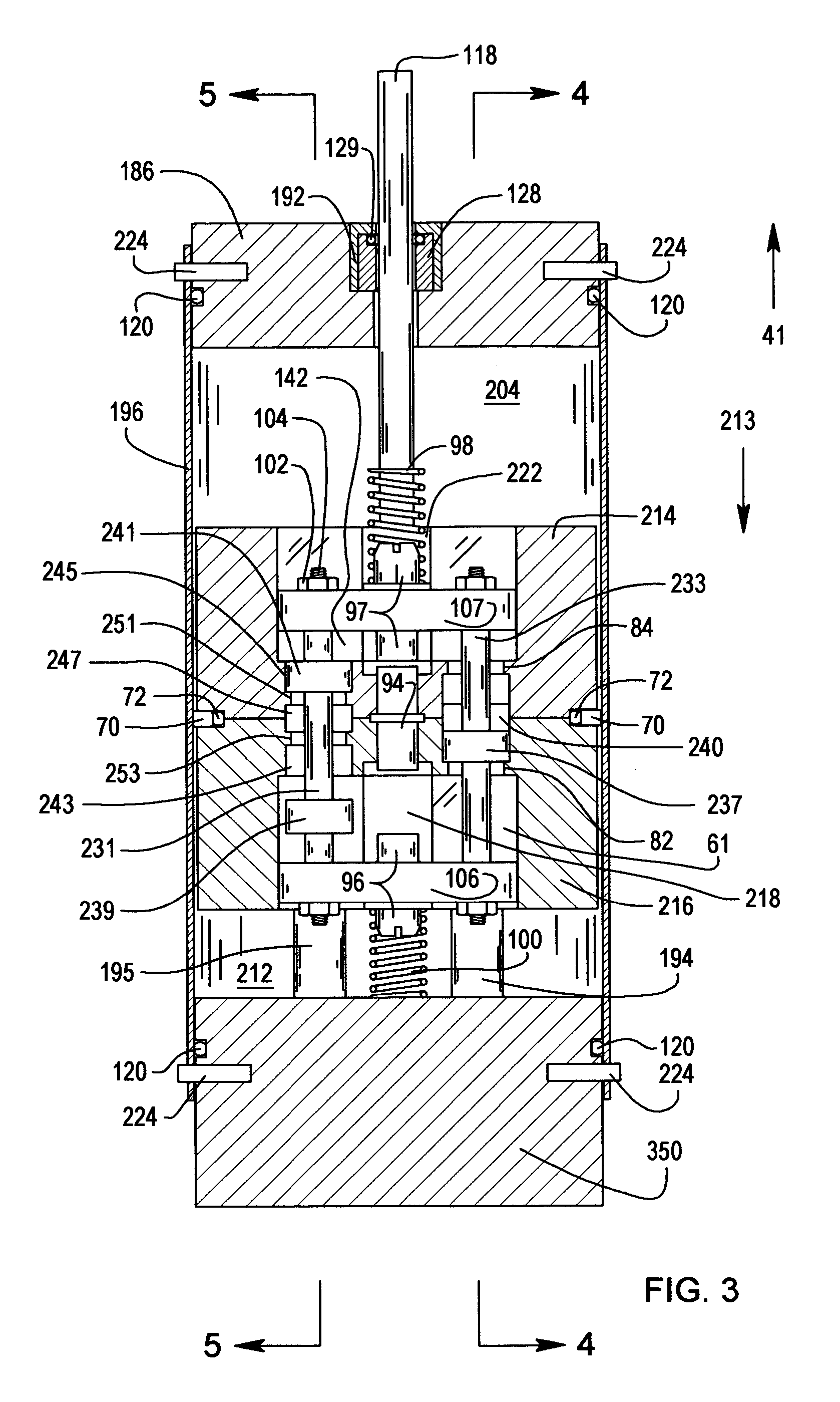
[0062]FIG. 1 shows a trimetric, general arrangement of an exemplary end port motor combined with an exemplary close coupled, shaft connected, fixed displacement pump in one exemplary embodiment of the present invention. A exemplary fluid motor housing is comprised of end cap 210, casing 196 and end cap 350. End cap 350 contains inlet port 180 and outlet port 182. End cap 350 and end cap 210 may be connected to casing 196 using any attachment system, including, for example, dowels 224.

[0063] An exemplary fluid pump is comprised of housing segments 228, 230 and 232. Segment 230 contains pump inlet port 162 and pump outlet port 236. Segments 232, 230, 228, and end cap 210 may be held together in compression by fastener...


PUM


Abstract

A device utilizing a fluid motor is disclosed. The device comprises a housing and a reciprocating piston in the housing. The piston and the housing may be configured to define at least two variable-volume chambers. A multi-port valve may be associated with the piston, and may be in communication with the at least two chambers. A valve actuating mechanism may be configured to actuate the multi-port valve to affect a fluid path in the device. The device may also include a valve engagement-release mechanism configured to maintain the multi-port valve in a position when the valve is not being actuated. An inlet port and an outlet port may be in selective communication with each piston chamber through the multi-port valve.

Description

[0001] This application claims the benefit of the filing date of U.S. Provisional Application No. 60 / 527,699, filed Dec. 6, 2003.FIELD OF THE INVENTION [0002] The present invention relates generally to fluid motor devices capable of converting a portion of the energy of a fluid flow into a reciprocating movement. More particularly, the present invention relates to devices comprised of a fluid motor coupled to a fluid pump. BACKGROUND OF THE INVENTION [0003] Fluid pumps may be powered by electric motors or by fluid motors. Fluid pumps driven by electric motors have a number of undesirable attributes. For example, in some applications, fluid pumps using electric motors are undesirable for safety reasons. For instance, when pumping solvents, acids, oils, and flammable liquids, it can be disadvantageous or even dangerous to operate high voltage or high current electric motors to drive the pumps. As another example, fluid pumps using electrical motors do not easily start from a stalled c...

Claims


Application Information

Patent Timeline
IPC IPC(8): F03C1/007F04B9/105F04B9/113
CPCF03C1/007F04B9/113F04B9/105
Inventor SMITH, CLYDE M.
Owner SMITH CLYDE M
Why Eureka
Try Eureka