Abrasion-resistant sleeve for wiring and the like

Inactive Publication Date: 2005-06-09
SOFANOU INC
View PDF21 Cites 84 Cited by
  • Summary
  • Abstract
  • Description
  • Claims
  • Application Information

AI Technical Summary

Benefits of technology

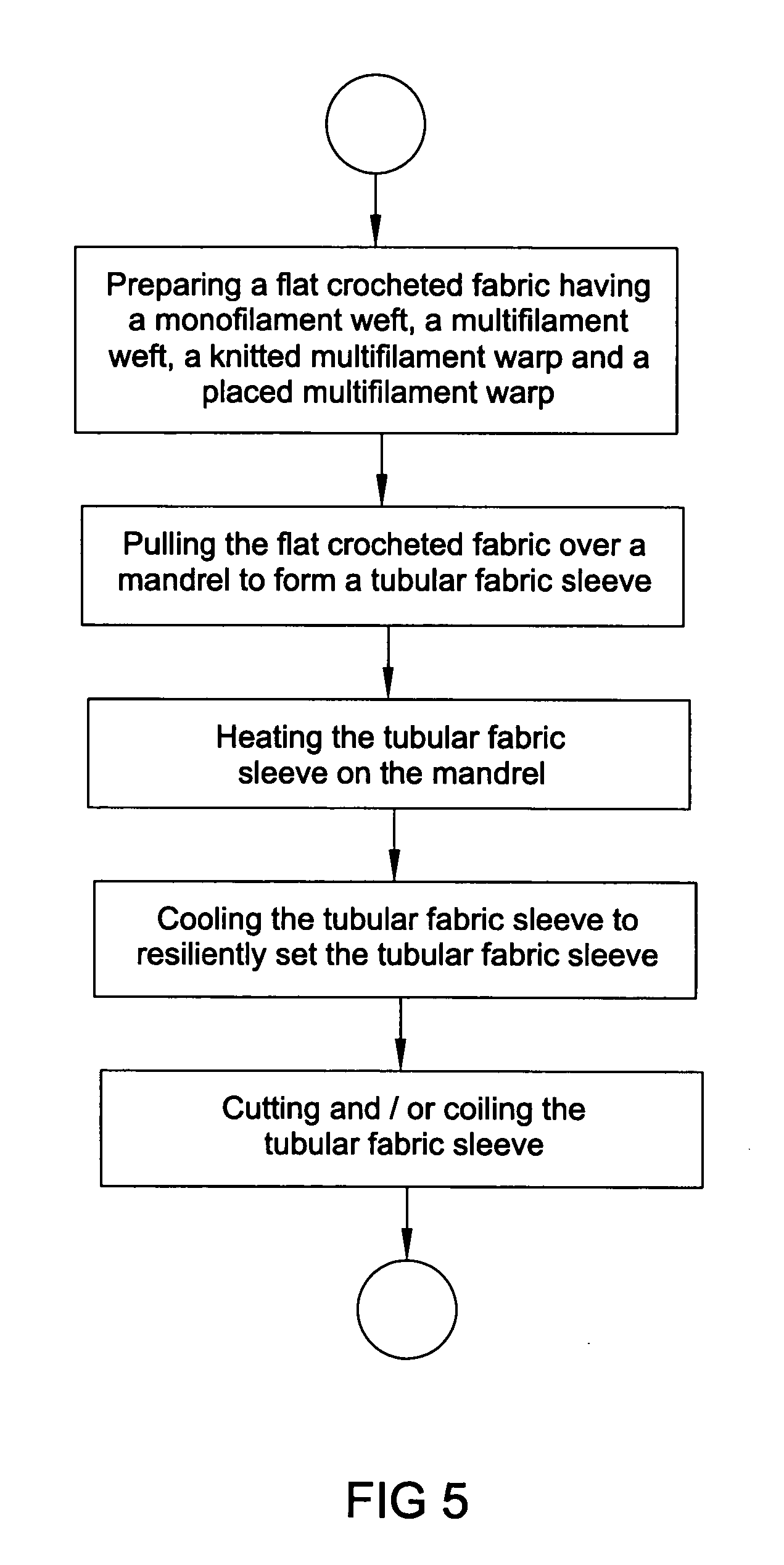
[0004] Accordingly, the present invention is directed to an abrasion-resistant tubular sleeve having a monofilament forming a first weft in the fabric cloth, a first multi-filament yarn forming a second weft in the fabric cloth, and a set of crocheted warps including a plurality of textured multifilament yarns forming a chain stitch lap in the fabric cloth. The fabric cloth is crocheted in a flat configuration and then formed with a heating setting operation into a resilient tubular sleeve. In one embodiment of the present invention, a series of polyamide monofilament and multifilament yarns are utilized to provide an abrasion resistant tubular sleeve. In a second embodiment, a polyethylene terephalate (PET) monofilament yarn is used in conjunction with a series of polyester multifilament yarns. The PET monofilament yarn and the polyester multifilaments yarns are treated with a flame-retardant to provide a self extinguishing, abrasion-resistant no-burn-rate tubular sleeve. In a third embodiment, a polyphenylene sulfide monofilament yarn is used in combination with a textured Nomex® / Basofil® blend yarn to provide a high-temperature, abrasion-resistant tubular sleeve. In a fourth embodiment, a polyamide monofilament is utilized in conjunction with a series of stainless steel / polyester blend yarns, and polyester multifilaments yarns to provide a shielded, abrasion-resistant tubular sleeve.

Problems solved by technology

However, many of the tubular sleeving designs require a specific fabrication for its given application.

Method used


Image

  • Abrasion-resistant sleeve for wiring and the like
  • Abrasion-resistant sleeve for wiring and the like
  • Abrasion-resistant sleeve for wiring and the like

Examples


Embodiment Construction

[0013] The following description of the preferred embodiments is merely exemplary in nature and is in no way intended to limit the invention, its application, or uses.

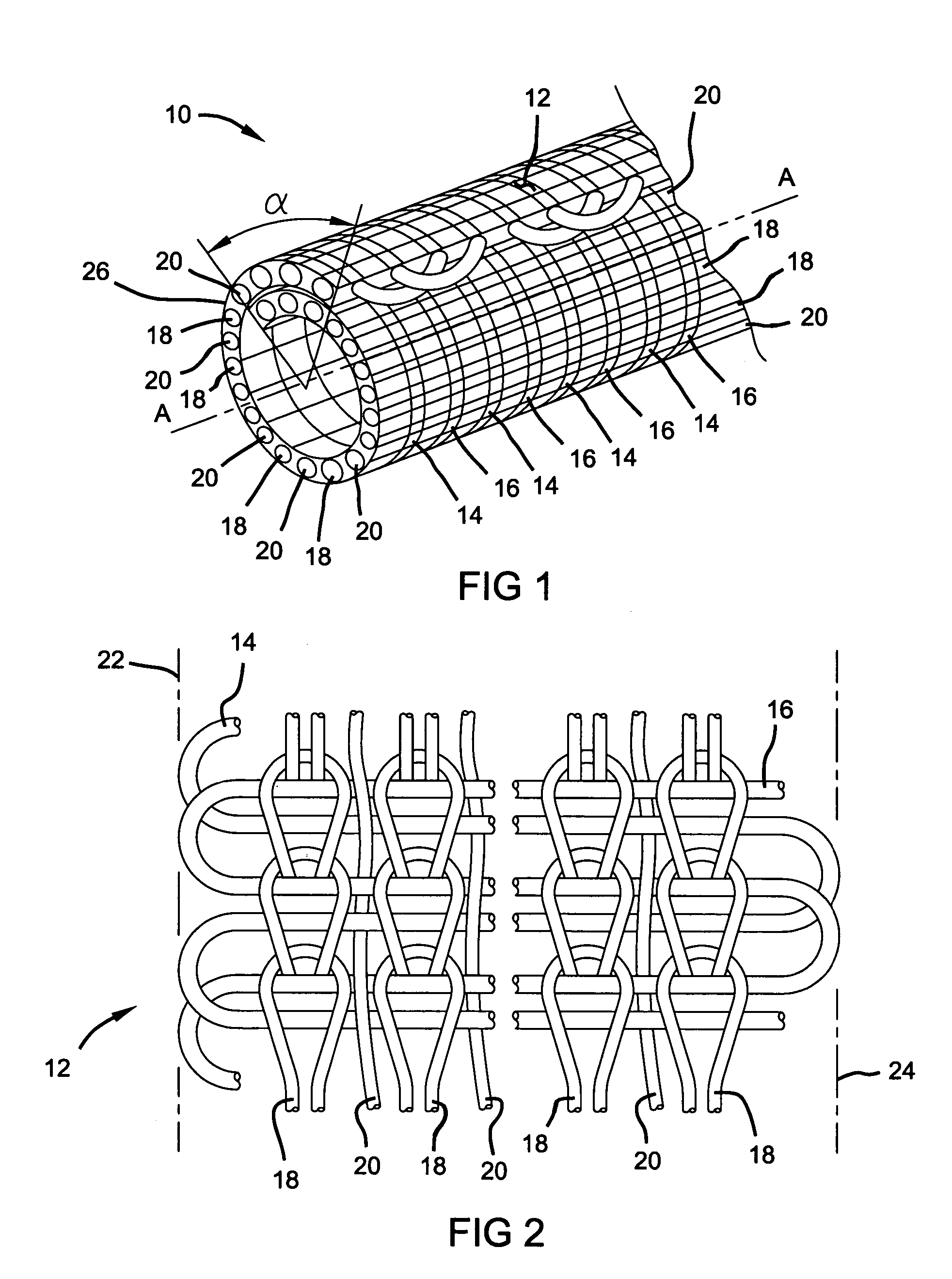
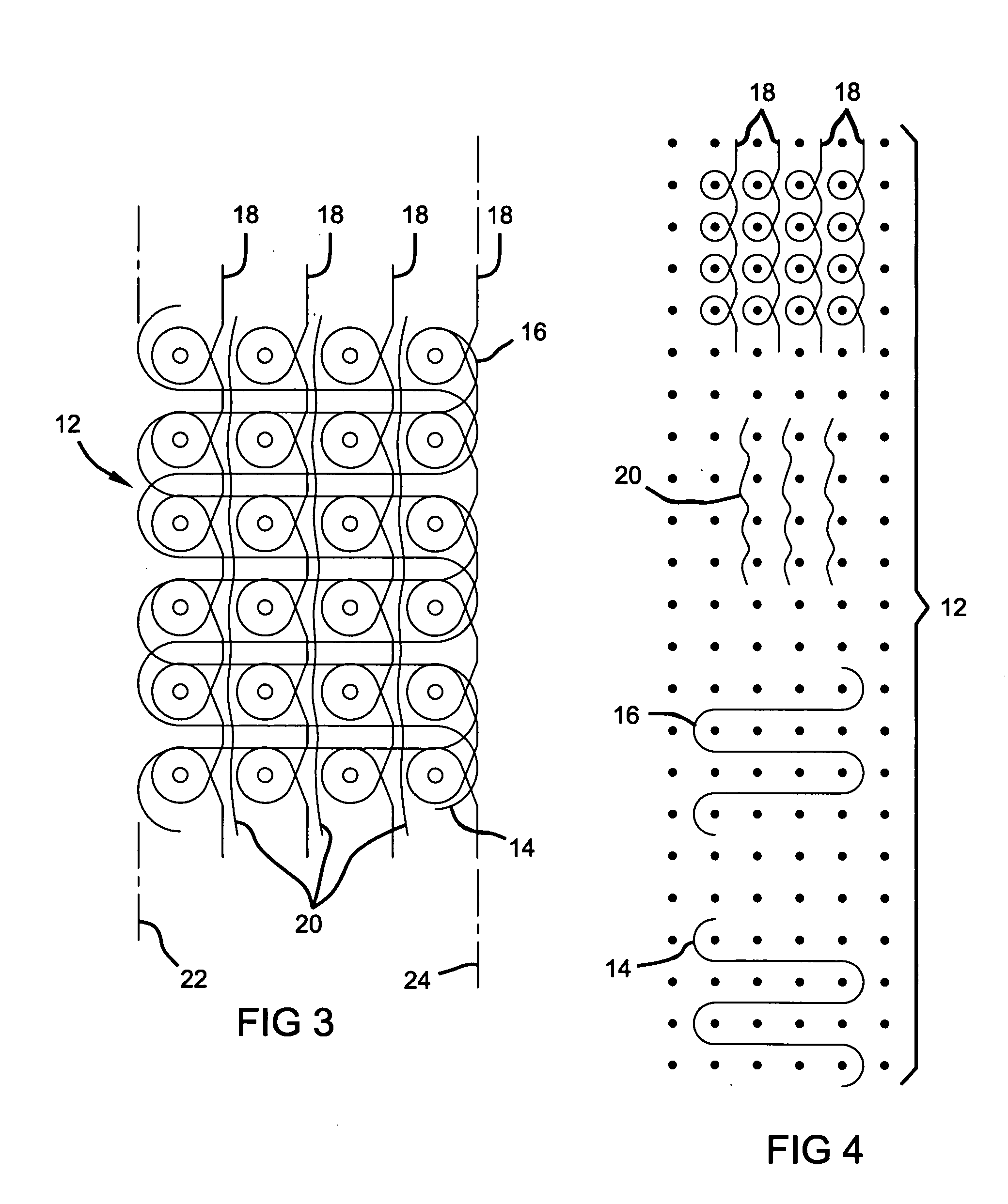
[0014] With reference to FIGS. 1-4, the present invention is directed to a generally flat crocheted fabric cloth 12 formed into a resilient sleeve which maintains its tubular shape. The fabric cloth 12 includes a monofilament yarn 14 forming a first weft and a textured multifilament yarn 16 forming a second weft in the fabric cloth 12. Fabric cloth 12 further includes a set of crocheted warps in the form of textured multifilament yarns forming a chain stitch lap 18 in the fabric cloth 12. In a preferred embodiment, the fabric cloth 12 further includes a set of placed warps including a plurality of multifilament yarns forming a lay-in stitch lap 20 in fabric cloth 12. The lay-in stitch lap 20 is utilized to fill the spacing on the face of the fabric cloth 12 in between the chain stitch lap 18 to provide a smoother surf...


PUM

PropertyMeasurementUnit
diameteraaaaaaaaaa
diameteraaaaaaaaaa
angleaaaaaaaaaa

Abstract

The present invention is directed to an abrasion-resistant tubular sleeve formed from a crocheted fabric cloth which is heat set into a resilient tubular sleeve. The fabric cloth is formed with a first monofilament weft and a second textured multifilament weft. A set of warps including a plurality of textured multifilament yarns forming a chain stitch lap is crocheted into the fabric cloth. Optionally, a textured multifilament yarn may be utilized as a placed or a lay-in warp in the fabric to provide further continuity on the face of the fabric cloth.

Description

FIELD OF THE INVENTION [0001] The present invention relates generally to a protective sleeve for covering a product subject to adverse environmental conditions and more particularly to a flat, knitted fabric cloth formed into a tubular fabric sleeve. BACKGROUND OF THE INVENTION [0002] Coverings for bundling loose items such as wiring, cables or tubing are generally known in the art. Such protective coverings include corrugated coverings, braided coverings and fabric coverings. To date, each of these types of tubular sleeves have been designed for and perform particularly well for a given function such as abrasion-resistance, flame retarding, high temperature or shielding of electromagnetic interference. However, many of the tubular sleeving designs require a specific fabrication for its given application. Thus, there remains a need for a common or universal means of fabricating a tubular sleeve in which the yarns within the sleeve are substituted, combined or interchanged based upon...

Claims


Application Information

Patent Timeline
Patent Type & Authority Applications(United States)
IPC IPC(8): D04B21/20
CPCD04B21/20D10B2505/12D10B2403/0311D10B2401/041D10B2403/02411D03D1/0043Y10T442/40
Inventor URIBARRI, PETER V.
Owner SOFANOU INC
Why Eureka
Try Eureka