
Apparatus, system, and method for managing reverse link communication

a reverse link and communication technology, applied in the field of communication systems, can solve the problems of increasing the transmission latency of the reverse link channel, affecting the average latency of all payload sizes, and affecting the transmission speed of the reverse link signal transmitted from the base station to the base station,

Active Publication Date: 2005-06-09
QUALCOMM INC
View PDF18 Cites 56 Cited by
  • Summary
  • Abstract
  • Description
  • Claims
  • Application Information

AI Technical Summary

Benefits of technology

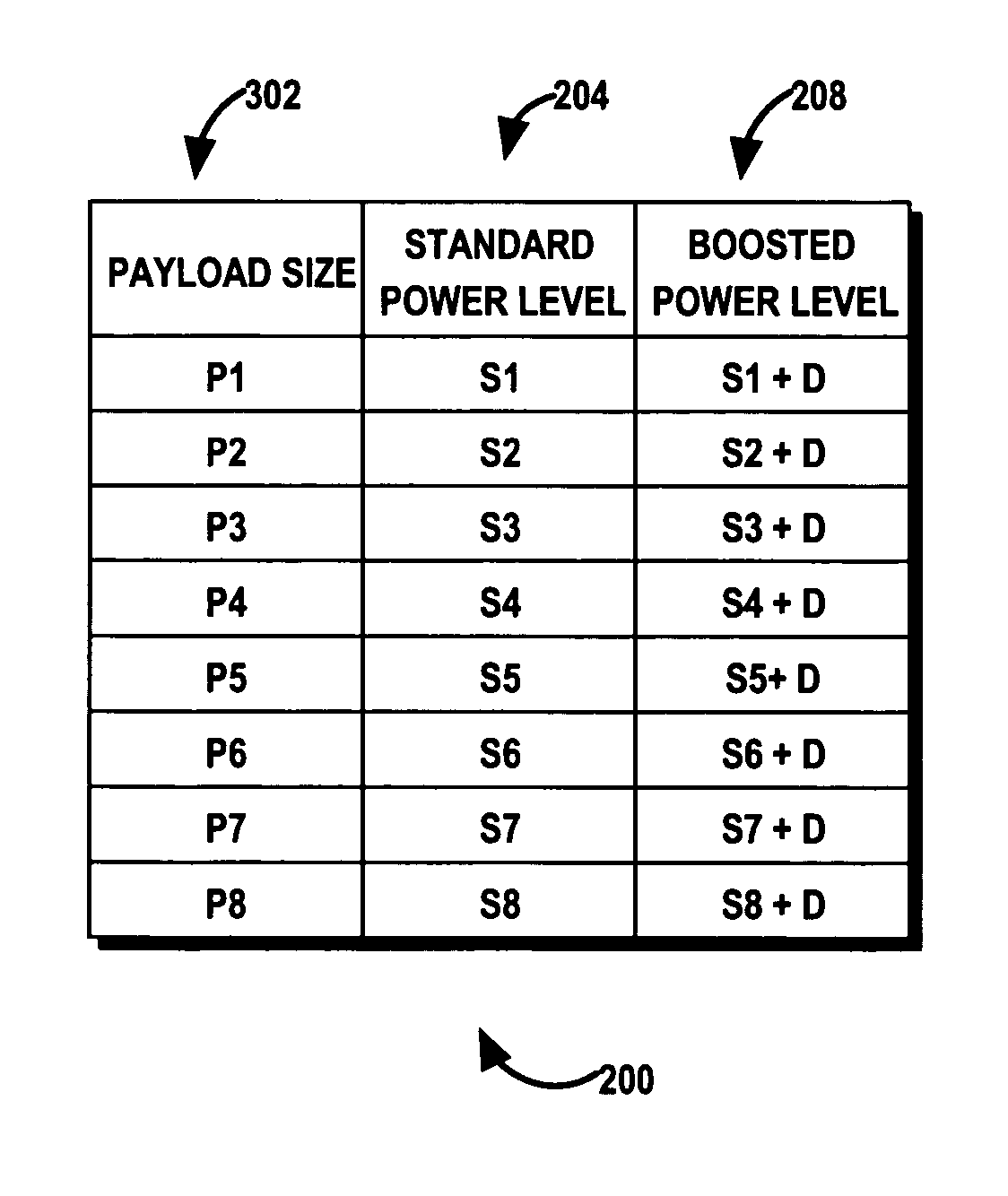
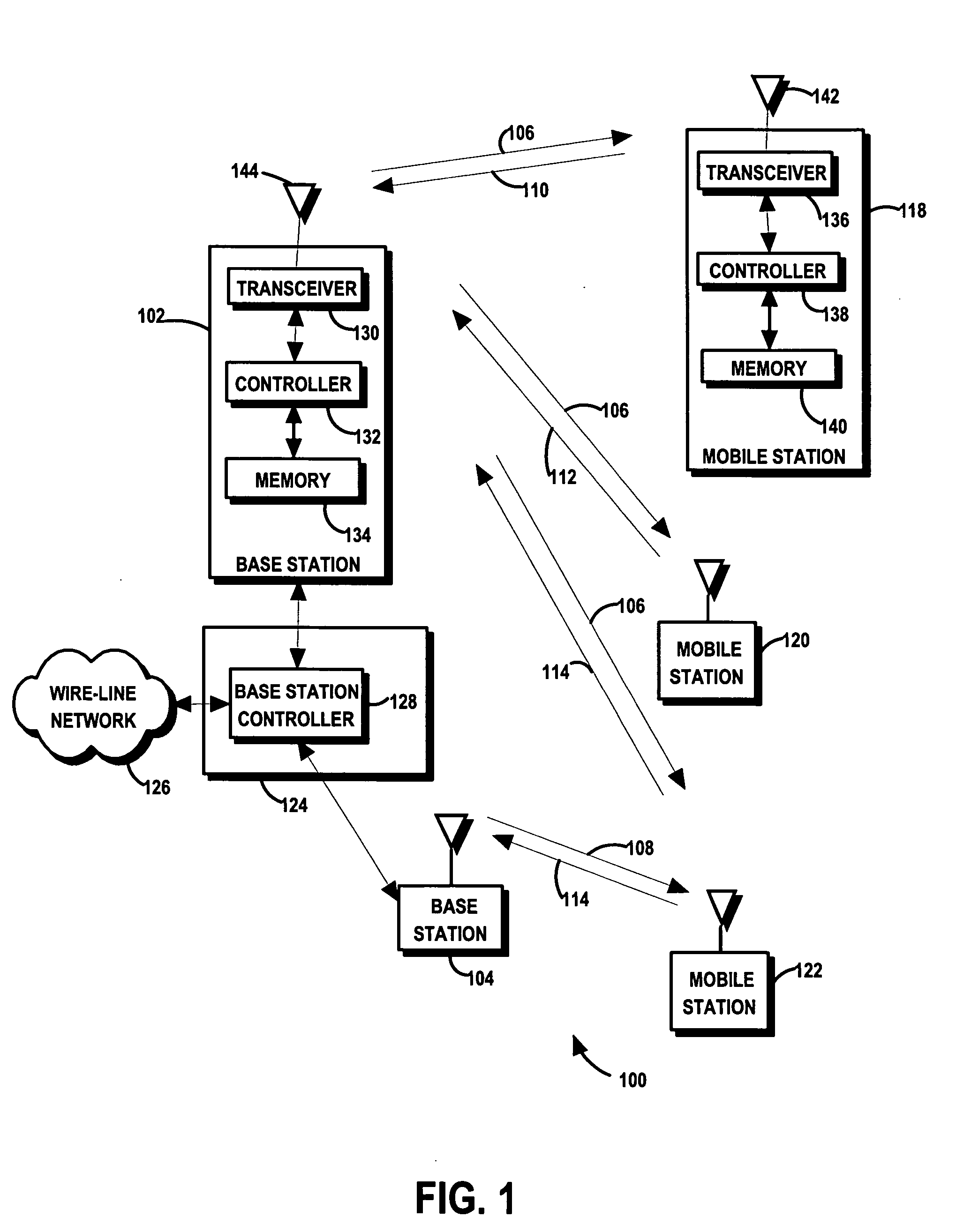
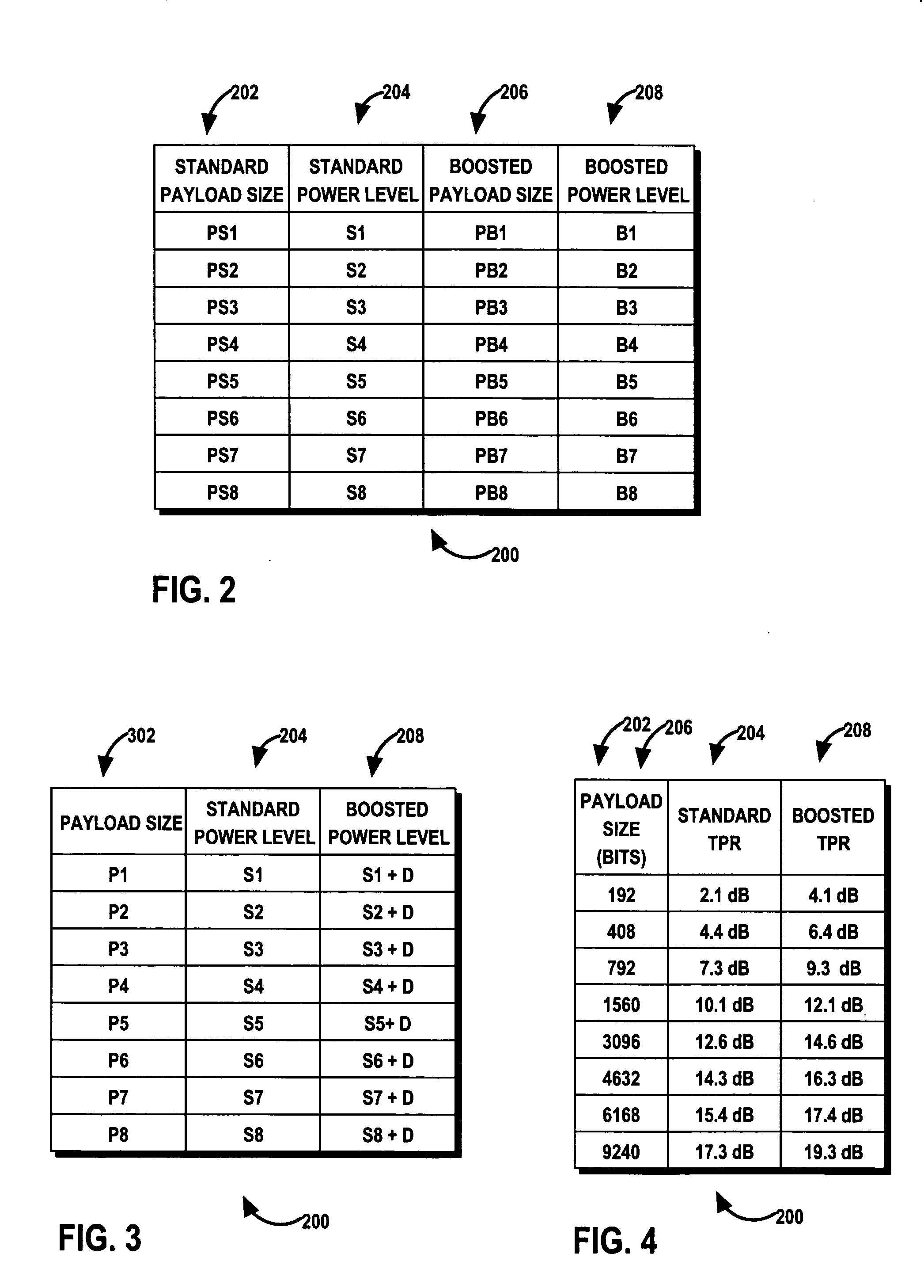
The invention is about managing reverse link resources in communication systems to improve performance. It allows a mobile station to select between transmitting a payload at a standard power level or a smaller payload at a boosted power level based on latency requirements of individual packets. This results in efficient use of reverse link resources and reduces latency on average. The invention also includes a method for managing reverse link resources based on reverse link transmission guidelines, which are derived from information received from a base station. Overall, the invention provides a mechanism for controlling the compromise between latency and system capacity in a distributed system using reverse link transmissions.

Problems solved by technology

In certain situations, the reverse link signals transmitted from each mobile station to a base station interfere with other reverse link signals transmitted from other mobile stations.
Conventional systems, however, are limited in that the retransmissions result in increased transmission latency on the reverse link channels.
For relatively smaller payloads, however, the mobile station is required to transmit at generally lower relative power levels resulting in approximately the same average latency times for all payload sizes.

Method used


Image

  • Apparatus, system, and method for managing reverse link communication
  • Apparatus, system, and method for managing reverse link communication
  • Apparatus, system, and method for managing reverse link communication

Examples


Embodiment Construction

[0012] In accordance with an exemplary embodiment of the invention, an apparatus, system, and method efficiently manage reverse link resources by allowing a mobile station to select between transmitting a payload at a standard power level and transmitting a smaller payload at a boosted power level. As a result, the mobile station can autonomously select a QoS (Quality of Service) level for individual packets based on delay requirements of individual packets. Based on reverse link transmission information received from a base station, the mobile station derives a reverse link transmission guideline defining the power levels and associated payloads for at least a standard service and boosted service. The mobile station selects a reverse link transmission power level from a plurality of power levels including at least a standard reverse link transmission power level associated with a standard payload size and a boosted reverse link transmission power level associated with a boosted pay...


PUM


Abstract

In accordance with an exemplary embodiment of the invention, an apparatus, system, and method efficiently manage reverse link resources by allowing a mobile station to select between transmitting a payload a standard power level and transmitting a smaller payload at a boosted power level. The mobile station, therefore, can autonomously select a QoS (Quality of Service) level for physical layer packets. Based on reverse link transmission information received from a base station, the mobile station derives a reverse link transmission guideline defining the power levels and associated payloads for at least a standard service and boosted service. The mobile station selects a reverse link transmission power level from a plurality of power levels including at least a standard reverse link transmission power level associated with a standard payload size and a boosted reverse link transmission power level associated with a boosted payload size where the standard payload size is greater than the boosted payload size.

Description

CLAIM OF PRIORITY UNDER 35 U.S.C. §119 [0001] This application claims the benefit of priority of Provisional Patent Application No. 60 / 501,563 filed on Sep. 8, 2003, entitled “Method And Apparatus for Traffic-to-Pilot Management for Code Division Multiple Access (CDMA) Reverse Link”, and Provisional Patent Application No. 60 / 501,450, filed on Sep. 8, 2003 entitled “Method And Apparatus for Traffic-to-Pilot Management for Code Division Multiple Access (CDMA) Reverse Link” both of which are incorporated by reference in its entirety herein. REFERENCE TO CO-PENDING APPLICATIONS FOR PATENT [0002] This application is related to U.S. patent application Ser. No. 10 / 853,638 filed on May 24, 2004 and entitled “Method and Apparatus for Controlling Reverse Link Data Rate of a Mobile Station in a Communication System with Reverse Link Common Rate Control”, which claims priority to Provisional Application No. 60 / 507,907, filed Sep. 30, 2003, entitled “Data Rate Control For Reverse-Link in a Commu...

Claims


Application Information

Patent Timeline
Patent Type & Authority Applications(United States)
IPC IPC(8): H04B7/005H04B7/185H04W52/14H04W52/24H04W52/26H04W52/28H04W52/36
CPCH04W52/146H04W52/245H04W52/367H04W52/265H04W52/288H04W52/26H04L5/0044H04L1/1812
Inventor LUNDBY, STEIN A.JAIN, AVINASHODENWALDER, JOSEPH P.SARKAR, SANDIPCHEN, TAOWEI, YONGBIN
Owner QUALCOMM INC
Learn More