Inflatable blanket with a tie

a blanket and tie technology, applied in the field of inflatable blankets, can solve the problems of not providing the desired further control of the movement of the blanket, positioned on the non-inflatable periphery, and often presenting the threat of hypothermia in surgery, and achieve the effect of greater movement control

Active Publication Date: 2005-06-09
STRYKER CORP
View PDF43 Cites 11 Cited by
  • Summary
  • Abstract
  • Description
  • Claims
  • Application Information

AI Technical Summary

Benefits of technology

[0009] The present invention is directed to at least one tie strap positioned on an inflatable blanket. These tie straps, when being used with the blanket, are positioned not on the non-inflatable periphery sections of the inflatable blanket, but on non-periphery sections, like an inflatable section, of the inflatable blanket. This is being done to provide the desired control of the blanket's movement and, if desired, the inflation of the blanket in certain areas of the inflatable blanket. Controlling the inflation of the blanket is obtained by the present straps ability to alter the size of at least a portion of an inflatable chamber within the inflatable blanket. The present ties also provide greater movement control because the tie straps provide desired pressure to at least one section of the inflatable blanket. The tie straps of the present invention are also an integral part of the blanket which means supplemental materials, like tape or ropes, are not needed to control the blanket with the present invention.

Problems solved by technology

Surgery often presents the threat of hypothermia.
In operation, heated air flows onto a patient's body from holes in the undersurface of the blanket, and the blankets do not form a self-supporting or Quonset hut-like structure.
The straps positioned on non-inflatable periphery positions, however, fail to provide desired further control of blanket's movement and inflation.

Method used


Image

  • Inflatable blanket with a tie
  • Inflatable blanket with a tie
  • Inflatable blanket with a tie

Examples


first embodiment

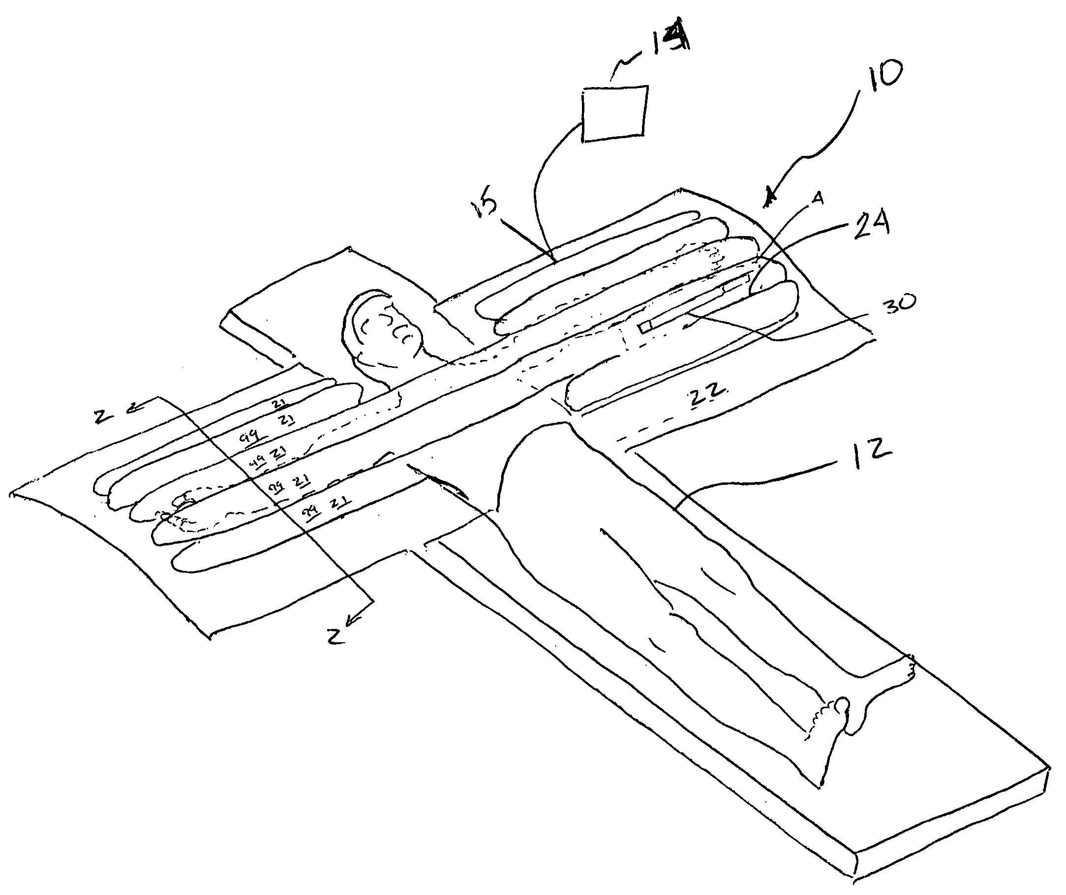
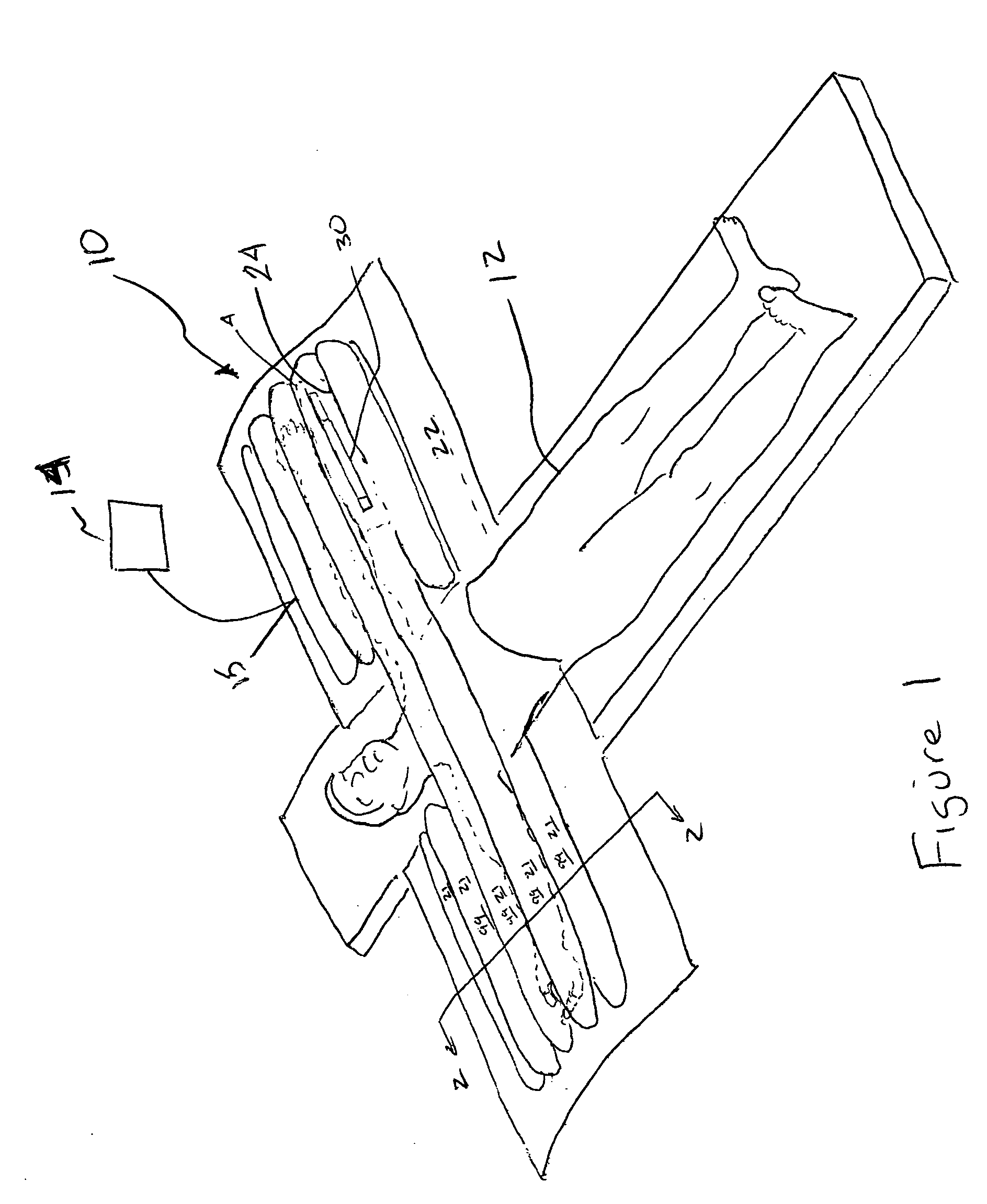
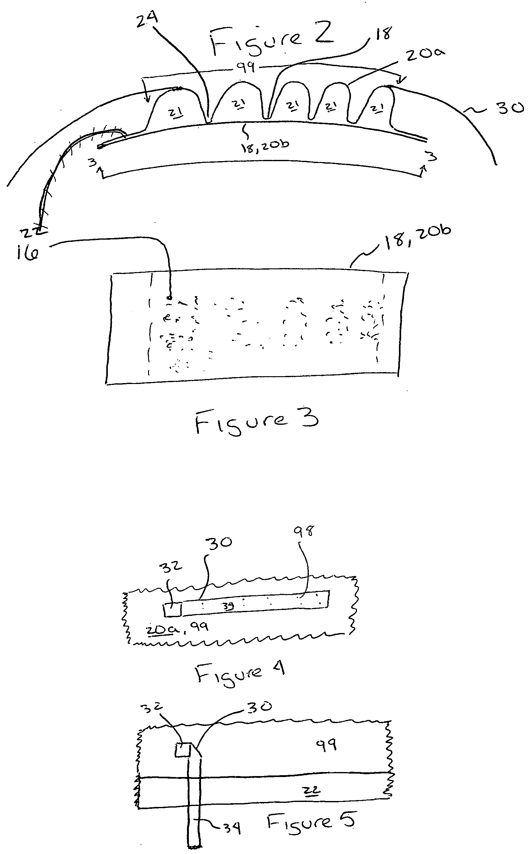
[0025]FIG. 2 illustrates a tie strap 30. The tie strap 30 is an elongated piece of material. The material can be the same material as used with the sheet material 20a,b, or 20a or 20b (if different) or similar material. A portion 32 of the strap 30 is designed to be permanently attached to a non-periphery section of the blanket 30.

[0026] The attachment portion 32 is sonic welded, heat welded, adhered, stapled, or equivalent thereof to the exterior surface (top surface or bottom surface, preferably the top surface) of the inflated section of the blanket 10. Preferably, the attachment portion 32 is sonic welded or heat welded to the inflated section 99. The remaining portion 34 of the strap 30 is easily removably welded, adhered, stapled, or tacked 98 to the blanket 30 as shown in FIG. 4.

[0027] When the blanket is being positioned on the patient, the remaining portion 34 is released from its removable attachment. The remaining portion is sufficiently long enough that it can go under...

second embodiment

[0028] The second embodiment is similar to the first embodiment except the remaining portion 34 extends in both directions from the attachment surface, as shown in FIG. 6.

third embodiment

[0029] The tie strap 30 is a removable section from the periphery 22 as shown in FIG. 7. By removable, we mean the tie strap 30 is extensively perforated 40 with the periphery 22, and designed to be removed from the periphery when used. The tie strap 30 has an attachment portion 32 and at least one remaining portion. The remaining portion can be designed like the first or second embodiments of the present invention.

[0030] The attachment portion 32 will have an adhesive, a hook / loop system 41, or equivalent thereof that attaches to a predetermined portion 42 of the inflatable section, preferably the top surface, of the blanket 10.


PUM


Abstract

The present invention is directed to at least one tie strap positioned on an inflatable blanket. These tie straps, when being used with the blanket, are positioned not on the non-inflatable periphery sections of the inflatable blanket, but on non-periphery sections, like an inflatable section, of the inflatable blanket. This is being done to provide the desired control of the blanket's movement and, if desired, the inflation of the blanket in certain areas of the inflatable blanket. Controlling the inflation of the blanket is obtained by the present straps ability to alter the size of at least a portion of an inflatable chamber within the inflatable blanket. The present ties also provide greater movement control because the tie straps provide desired pressure to at least one section of the inflatable blanket. The tie straps of the present invention are also an integral part of the blanket which means supplemental materials, like tape or ropes, are not needed to control the blanket with the present invention.

Description

FIELD OF THE INVENTION [0001] The present invention is directed to inflatable blankets having at least one tie and / or strap thereon. BACKGROUND OF THE INVENTION [0002] Gaymar Industries, Inc. is the assignee of the present application, and has been manufacturing, selling and offering to sell inflatable blankets for a number of years. On Jun. 8, 1999, Circuit Judge Rader wrote a court decision that described Gaymar's thermal blankets. That decision can be found at 181 F.3d 1291, 1304, 50 USPQ2d 1900, 1909 (Fed. Cir. 1999) and it clearly describes the differences between Gaymar's thermal blanket and at least one competitor's. In his outstanding decision, he wrote, “Convective thermal blankets inflate to direct warm (or cool) air onto a person. Surgeons often use these blankets during and after an operation to prevent or treat hypothermia caused by surgical conditions. Hypothermia results when a patient's body temperature drops below a certain threshold. Surgery often presents the thre...

Claims


Application Information

Patent Timeline
Patent Type & Authority Applications(United States)
IPC IPC(8): A61F7/00A61F7/02
CPCA61F7/0097A61F2007/0288A61F2007/006A61F2007/0001
Inventor PAOLINI, RAYMOND P.JUSIAK, JOEL T.
Owner STRYKER CORP
Why Eureka
Try Eureka