Fluid valve

Active Publication Date: 2021-02-18
SAFRAN AERO BOOSTERS SA
View PDF0 Cites 2 Cited by
  • Summary
  • Abstract
  • Description
  • Claims
  • Application Information

AI Technical Summary

Benefits of technology

This patent describes a valve that can be controlled by a computer to distribute fluid between two ways in proportion. The valve is compact, lightweight, and can be used with different fluids such as oil and fuel. It includes filters to prevent blockages and can be used in hydraulic circuits of aircraft. The technical effect of the patent is to provide a more efficient and compact valve for fluid distribution.

Problems solved by technology

Furthermore, if the stroke is not sufficient, the valve member could induce (even when the valve is fully open) excessively large pressure drops.
This increases the weight of the fluid valve.

Method used


Image

  • Fluid valve
  • Fluid valve

Examples


Embodiment Construction

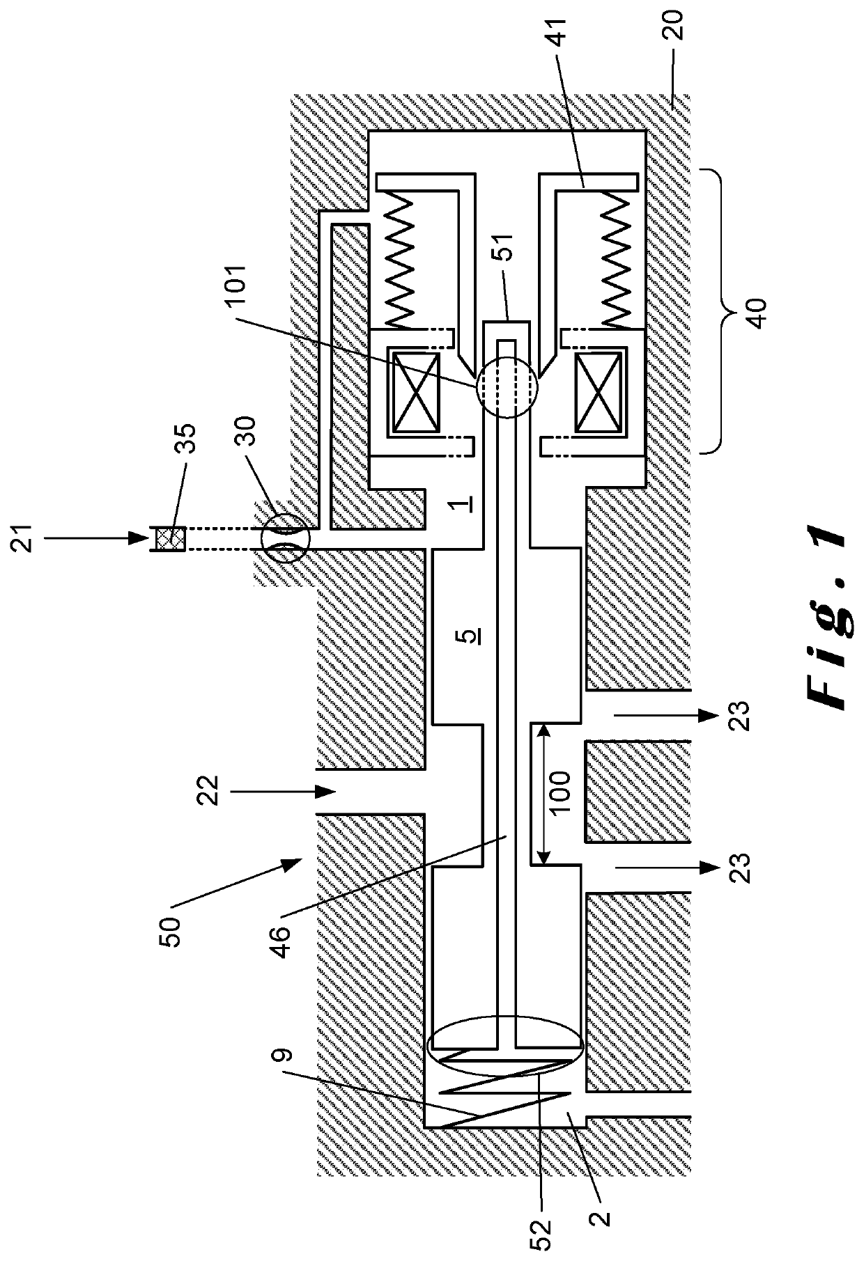
[0101]FIG. 1 shows an example of the embodiment of the fluid valve 50 according to the invention. It comprises a hollow valve body 20 and a three ways: one inlet 22 and two outlets 23. Preferably, the left-hand outlet 23 is a by-pass outlet, a term known to a person skilled in the art. Preferably, the right-hand outlet 23 is a engine outlet. The valve member 5 or slide is mobile in the hollow valve body 20. The shape of the valve member 5 with respect to the hollow of the hollow valve body 20 is such that a variation in the position of the valve member makes it possible to vary a fluid flow rate between the inlet 22 and one or both outlets 23. As shown in FIG. 1, one end of the valve member 5 is preferably connected or linked to the valve body 20 via a spring 9. The valve member 5 defines a first cavity 1 on its right and a second cavity 2 on its left at the spring 9. The second cavity 2 is preferably pressurized at the downstream pressure as shown in FIG. 1. The pressure in the fir...


PUM


Abstract

A fluid valve for a hydraulic circuit of an aircraft includes a valve body with an inlet and two outlets. The valve further includes a solenoid electric actuator with a ferromagnetic mobile driver and a valve member having a ferromagnetic portion / The valve member is movable within the valve body along a main direction and has first and second ends that define first and second cavities, respectively, on opposite sides of the valve member. A longitudinal cavity extends through the valve member parallel to the main direction and opens into the second cavity. Relative displacement between the mobile driver and the valve member modifies a communication between the longitudinal cavity and the first cavity via a side opening that is perpendicular to the main direction.

Description

TECHNICAL FIELD[0001]The invention relates to a proportional fluid valve, e.g. a three-way valve.BACKGROUND[0002]US2004 / 0163721A1 describes a fluid valve comprising a solenoid electric actuator. By injecting an electric current into the solenoid actuator, a driver called a push pin can be moved from a first position to a second position. This driver, which is not ferromagnetic in US2004 / 0163721A1, is connected to a ferromagnetic armature. A mobile valve member is connected to the driver and controls the passage of fluid between the inlet and outlet channels of the fluid valve. US2004 / 0163721A1 states in particular in the paragraph [0015] that the valve member is capable of moving in a manner equivalent to the driver.[0003]The valve described in US2004 / 0163721 A1 has disadvantages. For some applications, it is desirable that the valve member can describe a large movement or stroke. A large stroke of the valve member allows proportional control of larger flow rates. This is because, i...

Claims


Application Information

Patent Timeline
IPC IPC(8): F16K11/07F16K31/122F16K31/42
CPCF16K11/0716F16K31/1221F16K31/426F16K31/1223F16K31/1226F15B13/0435F16K31/1225
Inventor MAGETTE, ARNAUDVANDENBROUCKE, MAXIMEFRIPPIAT, CÉDRICBOMAL, JEAN-CHRISTIAN
Owner SAFRAN AERO BOOSTERS SA
Why Eureka
Try Eureka