Adjustable bone plate

a bone plate and adjustable technology, applied in the field of bone plate, can solve the problems of allowing an unacceptable bone movement, not easy to control, and small movement, and achieve the effects of resisting plate bending, better bone reconstruction or regrowth, and better control of the movement of the underlying bon

Inactive Publication Date: 2006-05-11
FIRST COMMERCE BANK
View PDF17 Cites 58 Cited by
  • Summary
  • Abstract
  • Description
  • Claims
  • Application Information

AI Technical Summary

Benefits of technology

[0007] It is an object of the invention to provide a two piece bone plate which provides a strong locking mechanism for fixing the overall length of the plate, and resisting bending of the plate.
[0008] It is a further object of the invention to provide a bone plate which has an adjustable length, to permit the surgeon to fix the clinically effective length of the plate, permitting a better reconstruction or re-growth of bone at the fracture.
[0009] It is a further object of the present invention to provide a bone plate which resists bending, an thereby permits the surgeon better control of the movement of the underlying bone while adjusting the length of the plate.
[0010] It is still a further object of the present invention to provide a controlled method for bringing together the pieces of bone using a two piece bone plate, while controlling the turning of the bone.

Problems solved by technology

The laterally adjacent prongs do not permit the surgeon to see the fracture surfaces coming together under the bone plate.
Further, the use of only one locking screw permitted the assembled plate to twist longitudinally, permitting an unacceptable movement of the bone.
This movement, however, was slight, and not easily controllable.

Method used


Image

  • Adjustable bone plate
  • Adjustable bone plate
  • Adjustable bone plate

Examples


Embodiment Construction

[0032] The preferred embodiments of the present invention will now be described with reference to FIGS. 1-14 in of the drawings. Identical elements in the various Figures are designated with the same reference numerals.

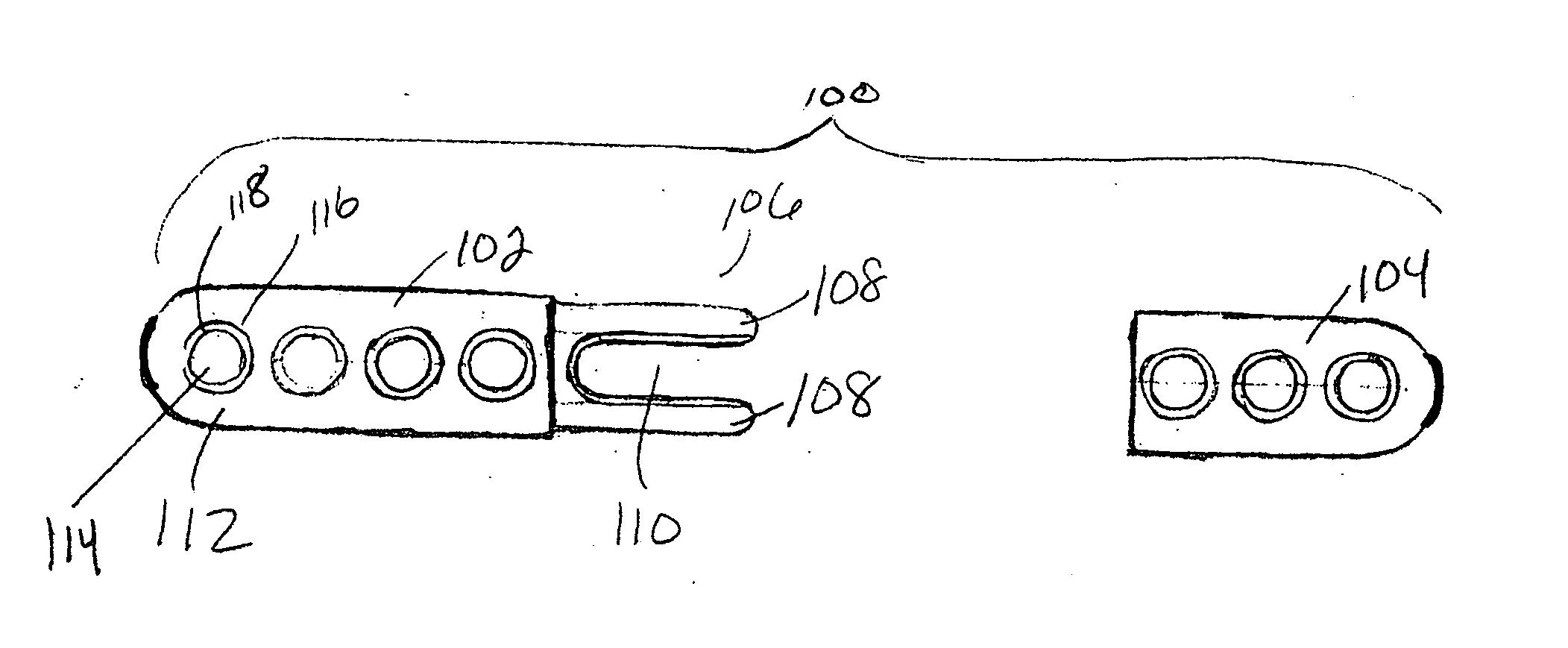
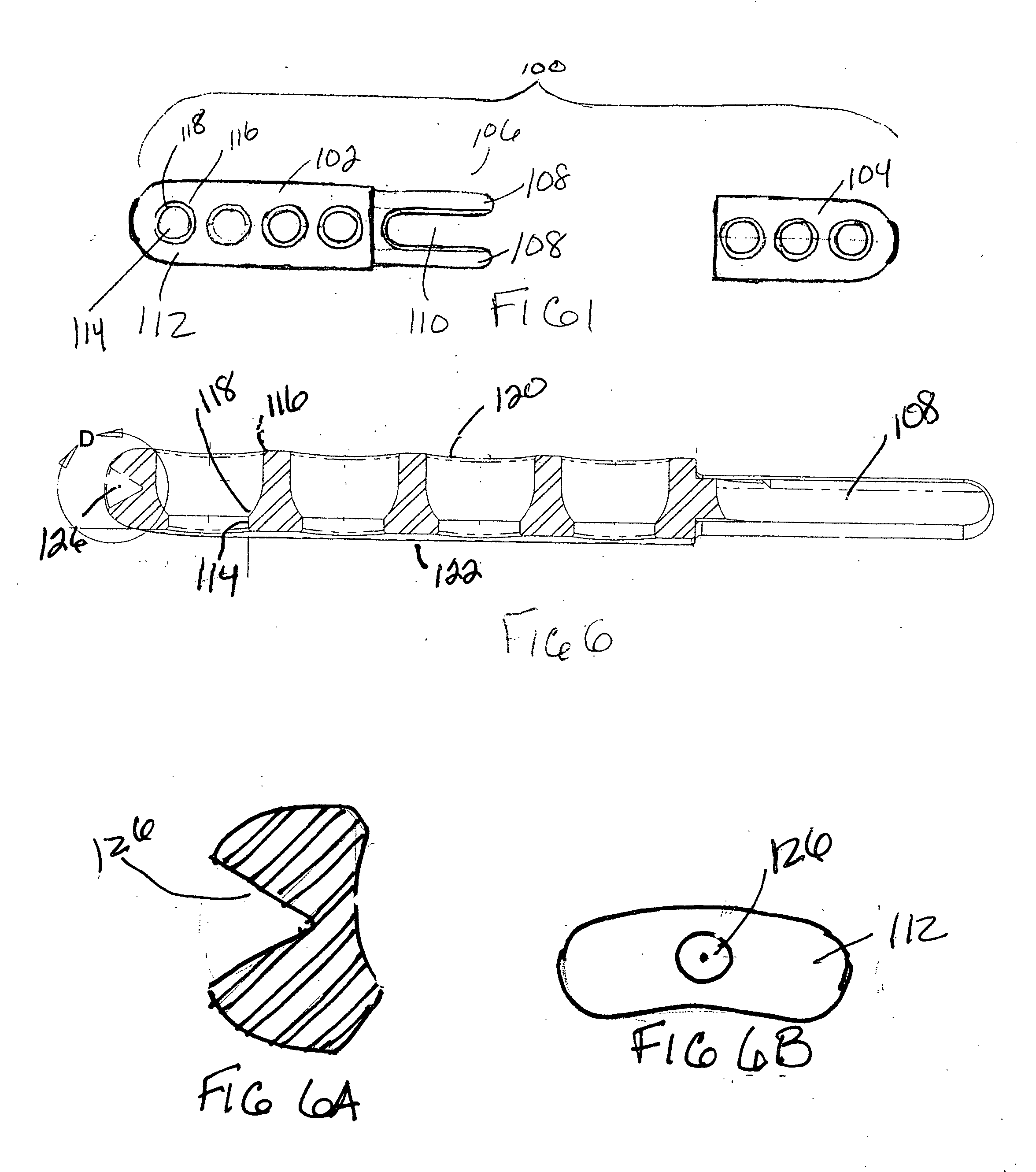
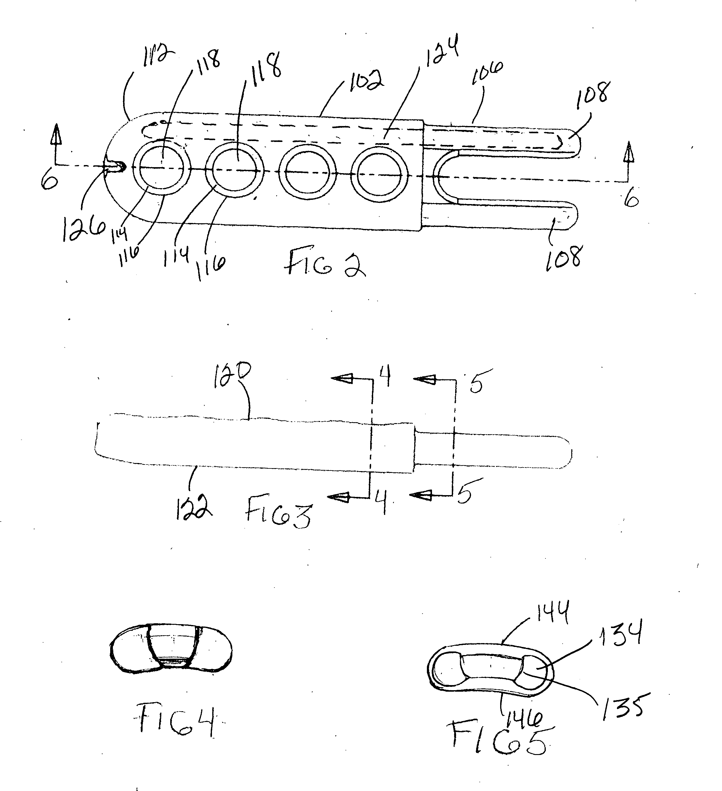
[0033] As shown in FIG. 1 the sliding bone plate assembly, 100, of the present invention is comprised of a first longitudinal plate, 102, and a second longitudinal plate, 104. The first longitudinal plate has an end, 106, defined by at least two spaced prongs, 108. The spacing of the prongs permits an observation window, 110, between the prongs and the plates. As may be seen in FIG. 5, the prongs 108 are located at the lateral edges of the plate to open up the window, 110.

[0034] The other end, 112, of the first longitudinal plate comprises means for fastening the plate to a body structure, such as, for example, a bone. In this particular embodiment the means comprises threaded through holes, 114, for receiving bone screws, not shown. The assembly may further include...


PUM


Abstract

A longitudinally curved adjustable bone plate comprising name to play how will the first plate having an end defined by at least two spaced prongs, and an end having means to fasten the plate to a body structure, e.g., the bone; and a second plate having an end defined by at least two straight bores for receiving the prongs, and an end having means to fasten the plate to a body structure, e.g., a bone; and a locking assembly for locking the prongs in the bores and fixing the overall length of the plate.

Description

FIELD OF THE INVENTION [0001] The present invention relates to bone plates for holding body structures, such as the bones affixed relative to one another. More particularly this invention relates to longitudinal bone plate assemblies wherein the length of the plate is adjustable. BACKGROUND OF THE INVENTION [0002] Bone plates come in many sizes and shapes. The typical bone plate has a fixed dimension, and multiple holes for accommodating bone screws. In use, the surgeon brings together the fractured bone, places the bone plate atop the fracture, and inserts bone screws through the holes in the plate which overlie the healthy part of the bone, securing the bone about the fracture. Bone plates of many sizes are provided for the surgeon, and each is supplied with a number of holes so that the surgeon can arrange the plate over the fracture and have bone screw holes available above the healthy bone. [0003] U.S. Pat. No. 6,666,867 describes a bone plate having an adjustable length. The a...

Claims


Application Information

Patent Timeline
Patent Type & Authority Applications(United States)
IPC IPC(8): A61F2/30
CPCA61B17/80A61B17/8023A61B17/8052A61B17/58A61B17/70A61F2/30
Inventor RALPH, JAMES D.TROXELL, THOMAS N.TATAR, STEPHEN L.
Owner FIRST COMMERCE BANK
Why Eureka
Try Eureka