
Lane keep control apparatus and method for automotive vehicle

a technology for keeping control apparatus and vehicles, applied in anti-collision systems, non-deflectable wheel steering, underwater vessels, etc., can solve the problems that the driver cannot recognize that the vehicle has the tendency to deviate from the traffic lane, and the natural purpose of arranging the rambling strip on the traveling road surface cannot be achieved

Inactive Publication Date: 2005-06-09
NISSAN MOTOR CO LTD
View PDF18 Cites 86 Cited by
  • Summary
  • Abstract
  • Description
  • Claims
  • Application Information

AI Technical Summary

Benefits of technology

[0007] It is, therefore, an object of the present invention to provide improved lane keep control apparatus and method for an automotive vehicle which are capable of having the driver himself carry out the operation to avoid the deviation of the vehicle from the traffic lane with the traffic lane deviation recognized for the driver while avoiding the deviation of the vehicle from the traffic lane.

Problems solved by technology

However, in a case where the lane keep control apparatus controls the vehicle in a direction in which the deviation from the traffic lane is avoided, as often the case, the driver cannot recognize that the vehicle has the tendency of deviating from the traffic lane.
The natural purpose of arranging the rambling strip on the traveling road surface cannot be achieved.

Method used


Image

  • Lane keep control apparatus and method for automotive vehicle
  • Lane keep control apparatus and method for automotive vehicle
  • Lane keep control apparatus and method for automotive vehicle

Examples


first embodiment

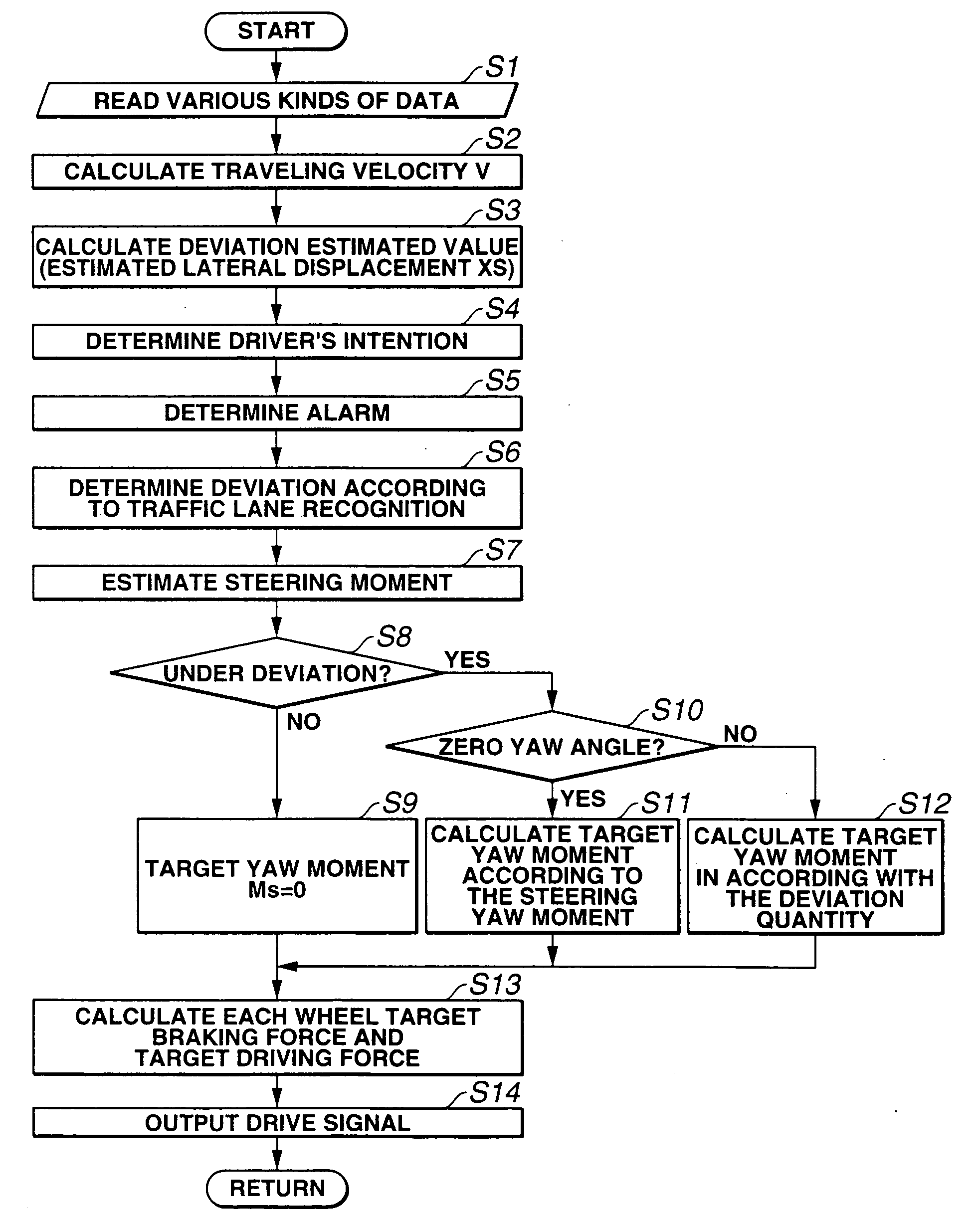
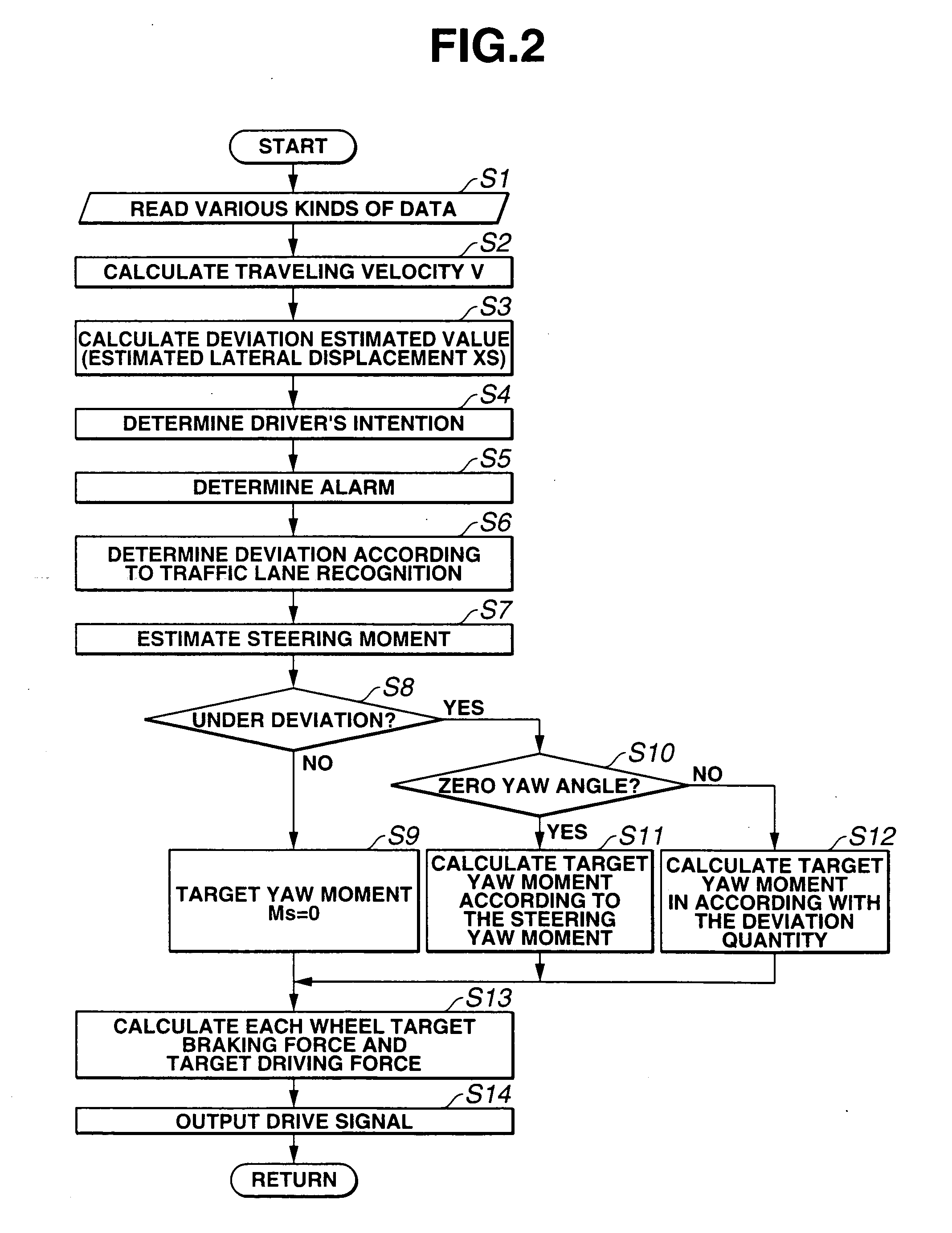
[0049] Next, an operation of the first embodiment will be described below. Suppose now that the vehicle is traveling on the center of the traveling traffic lane. In this case, deviation estimated value XS calculated at step S3 satisfies neither XS>Xw nor XS5. Since neither XS≧Xc nor XS≦−Xc, deviation determination flag is set as FLD=0 at step S6. In addition, the estimation of steering moment is carried out on the basis of the instantaneous steering angle δ at step S7. At this time, since the traffic lane deviation is not carried out, the routine goes from step S8 to step S9. Since deviation determination flag FLD=0 and the vehicle is not in the traffic lane deviation tendency, target yaw moment Ms is set as Ms=0. Hence, the yaw moment due to the deviation preventive control is not developed. In details, in a case where the vehicle is not in the traffic lane deviation tendency, the yaw moment due to the deviation preventive control is not acted so that the vehicle behaves according ...

second embodiment

[0067] Next, the operation in the case of the second embodiment will be described below. Suppose now that the host vehicle is traveling on the traveling traffic road where the recess-and-convex portion is disposed along (on) the traffic lane block line or in the proximity to (or along) the traffic lane block line as shown in FIG. 13A. At this time, in a case where the host vehicle is traveling on the center of the traffic lane, deviation estimated value XS calculated at step S3 satisfies neither XS>Xw nor XS5. In addition, since neither XS≧Xc nor XSLD is set as FLD=0 (at step S6a). Then, since any road wheel of the host vehicle is not traveling on the recess-and-convex portion, the road wheel acceleration dVwi is not periodically vibrated. Recess-and-convex determination flags Fot1 and Fot2 are both set to zeroes (“0”), the host vehicle is determined to be not placed on the road end, and road end flag is set as Fdw=0 (steps S21, S22).

[0068] Then, at this time, since the host vehicle...


PUM


Abstract

In lane keep control apparatus and method for an automotive vehicle, a deviation tendency detecting section detects whether the vehicle has a tendency of a deviation from a traveling traffic lane and a deviation avoidance controlling section performs a control for the vehicle to travel on a road surface which is parallel to the traveling traffic lane when the deviation tendency detecting section detects that the vehicle has the tendency of the deviation from the traveling traffic lane and, thereafter, performs a control to prevent a yaw angle of the vehicle with respect to the traveling traffic lane from increasing in a direction in which the tendency of the deviation becomes large.

Description

BACKGROUND OF THE INVENTION [0001] 1. Field of the Invention [0002] The present invention relates to lane keep control apparatus and method for an automotive vehicle which are capable of preventing a deviation of the vehicle from a traveling traffic lane on which the vehicle is traveling when the vehicle is about to deviate from the traffic lane during a travel. [0003] 2. Description of the Related Art [0004] A Japanese Patent Application First Publication No. Heisei 11-180327 published on Jul. 6, 1999 exemplifies a previously proposed lane keep control apparatus. In the previously proposed lane keep control apparatus, a steering actuator is controlled in accordance with a lateral deviation quantity which is a distance from a reference position of the traffic lane on which the vehicle is traveling to a traveling position of the vehicle (the vehicle is also hereinafter called a host vehicle), for example, when the host vehicle has a tendency of deviating from the traffic lane so as t...

Claims


Application Information

Patent Timeline
Patent Type & Authority Applications(United States)
IPC IPC(8): B60R21/00B60T8/1755B60T8/58B60W10/04B60W10/18B60W10/188B60W10/20B60W30/00B60W30/12B62D6/00B62D15/02B62D101/00B62D111/00B62D113/00G06F7/00G08G1/16
CPCG08G1/16G08G1/167B60T8/1755B62D15/029B60T2201/084B60T2201/087B60W30/12B60T2201/08
Inventor MATSUMOTO, SHINJITANGE, SATOSHISHIMAKAGE, MASAYASU
Owner NISSAN MOTOR CO LTD
Learn More