Unlock instant, AI-driven research and patent intelligence for your innovation.

PCI express switch

Inactive Publication Date: 2005-06-09
TEXAS INSTR INC
View PDF5 Cites 42 Cited by
  • Summary
  • Abstract
  • Description
  • Claims
  • Application Information

AI Technical Summary

Problems solved by technology

The implementation of this technology has come close to its practical limits of performance and can not easily be scaled up in frequency or down in voltage.
However, storing the data in the buffer memory in this manner is very inefficient.
This additional memory increases the size of the integrated circuit chip and therefore the cost thereof as well as reducing the yields from the manufacturing process.

Method used


Image

  • PCI express switch
  • PCI express switch
  • PCI express switch

Examples


Embodiment Construction

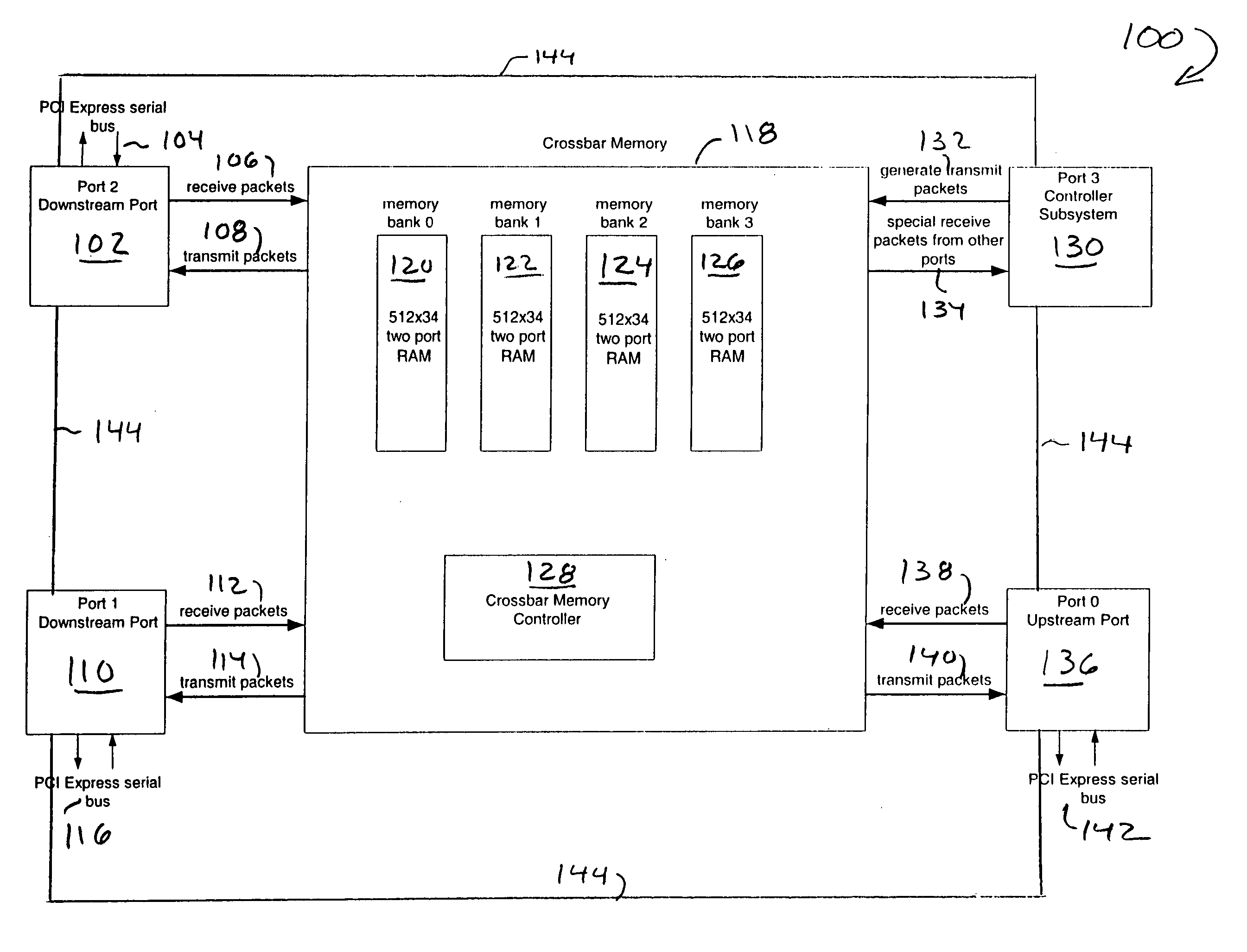
[0021]FIG. 1 illustrates a block diagram of a PCI Express switch according to the present invention generally as 100. The PCI Express switch has a port 0 which is the upstream port for transmitting and receiving data from other devices on the PCI Express fabric. The PCI Express switch also has 2 downstream ports, ports 1 and 2, which are coupled via PCI Express serial busses to other devices on the PCI Express fabric. The switch also has a controller subsystem 130 which is virtual port, illustrated as port 3, for the system. The controller subsystem has the intelligence for the switch and would typically contain a microcontroller. The controller subsystem 130 is in communication with the other ports, port 0, port 1 and port 2 via an internal bus 144. This internal bus provides a control path which is utilized by the controller subsystem 130 to set the configuration for the ports 0, 1 and 2 on power up of the system, to check the status of each of the port, to process transactions wh...


PUM


Abstract

A PCI Express switch utilizes a central crossbar memory for all ports of the switch. The crossbar memory retains the packet that is to be sent out and only the head pointer for the packet is transmitted to the transmission port. The crossbar memory can also be used as the replay memory for the switch. A circuit for choosing the head pointer at a port for the packet to be sent out, is also disclosed.

Description

REFERENCE TO RELATED APPLICATIONS [0001] This application is related to U.S. application Ser. No. ______ (TI-36016) filed on even date and, entitled “A Weighted-Round Robin Arbitrator”, which is incorporated herein by reference.FIELD OF THE INVENTION [0002] This invention relates to a network switch and more specifically to a network switch for a PCI Express fabric. BACKGROUND OF THE INVENTION [0003] Peripheral Component Interconnect (PCI) is a parallel bus architecture developed in 1992 which has become the predominant local bus for personal computers and similar platforms. The implementation of this technology has come close to its practical limits of performance and can not easily be scaled up in frequency or down in voltage. A new architecture utilizing point-to-point transmission, having a higher speed, and which is scalable for future improvements, is known as PCI Express. [0004] A PCI Express switch receives data from other network components on a PCI Express fabric and route...

Claims


Application Information

Patent Timeline
IPC IPC(8): G06F13/00G06F13/40
CPCG06F13/4027
Inventor LI, STEPHEN H.DENG, BRIAN TSEHOWARD, PAULKIMBLE, DAVE
Owner TEXAS INSTR INC
Features
  • R&D
  • Intellectual Property
  • Life Sciences
  • Materials
  • Tech Scout
  • Unparalleled Data Quality
  • Higher Quality Content
  • 60% Fewer Hallucinations
Learn More