Disk convey apparatus

a technology of conveying apparatus and disk, which is applied in the direction of information storage, instruments, data recording, etc., can solve the problems of difficult to transfer the disk with high stability, the inconvenient use of one desk drive in both horizontal installation and vertical installation, and the troublesome work of the disk setting/removal work in which the disk is set to or removed from the tray, etc., to achieve the effect of simple constitution of engagement and reliable switching to each other

Inactive Publication Date: 2005-06-09
PANASONIC CORP
View PDF7 Cites 3 Cited by
  • Summary
  • Abstract
  • Description
  • Claims
  • Application Information

AI Technical Summary

Benefits of technology

[0033] According to the eleventh aspect of the present invention, basically the same function and effect as the tenth aspect can be obtained. Specifically, the disk guide is provided with a projection capable of engaging with a groove provided in the clamp board, and the projection of the disk guide is guided by the groove formed in the clamp board thereby the rotational position of the disk guide is changed. And, the urging state of the disk against the first disk support member is released when both of the first and second disk support members are disposed at the first position. That is, the urging state of the disk against the first disk support member and the released state thereof can be reliably switched to each other by a relatively simple constitution of an engagement between the projection provided on the disk guide and the guide groove provided in the clamp board.

Problems solved by technology

However, in this constitution of the disk transfer device, there is a problem that disk setting / removal works in which a disk is set to or removed from the tray are very troublesome.
Further, in the above-described constitution of the disk transfer device, it is very inconvenient to use one desk drive in both horizontal installation and vertical installation depending upon the purpose to use or the installed place and the like.
Accordingly, it is difficult for the disk to be held with high stability and transferred with no wobbly movements when it is in the vertical position.

Method used


Image

  • Disk convey apparatus
  • Disk convey apparatus
  • Disk convey apparatus

Examples


Embodiment Construction

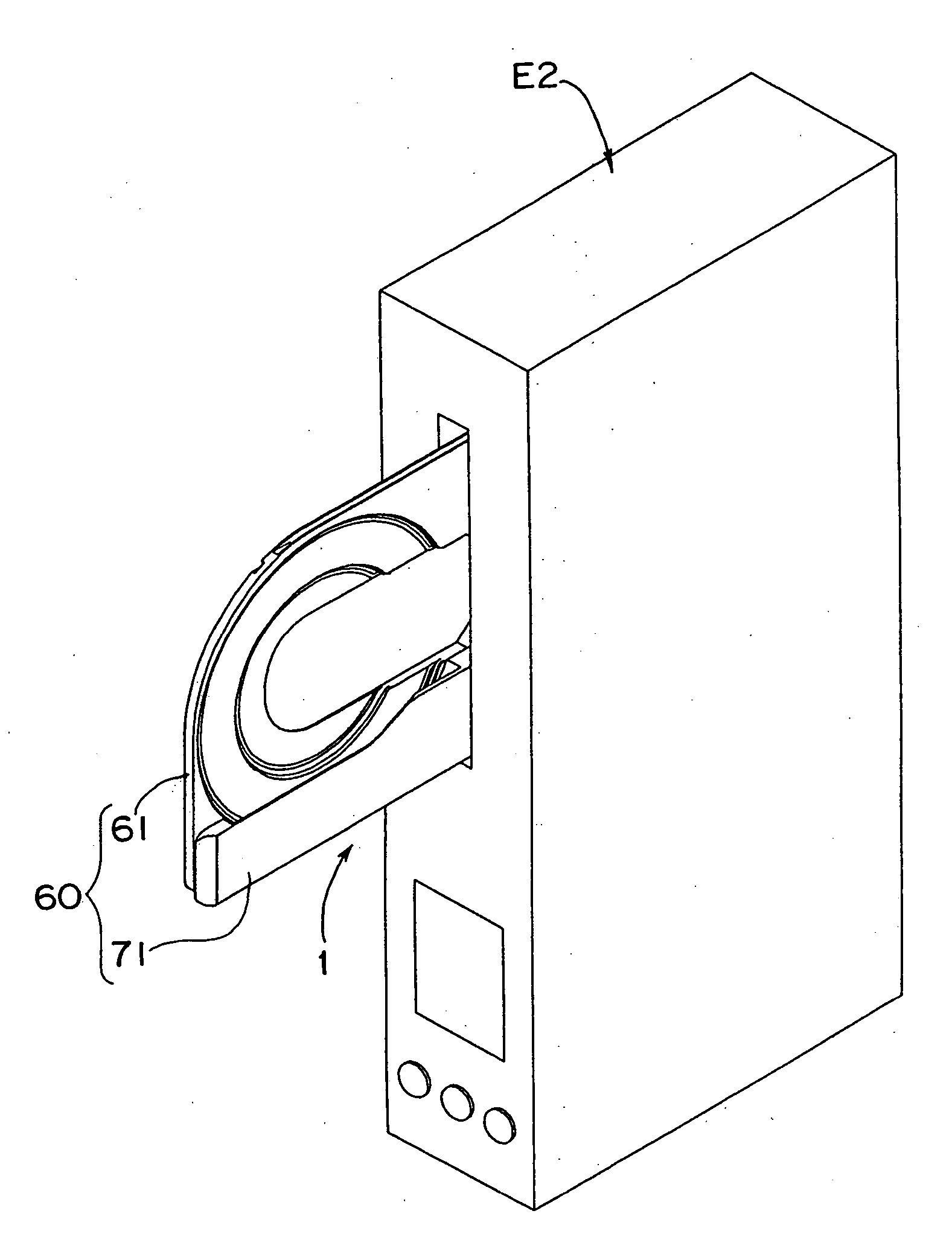
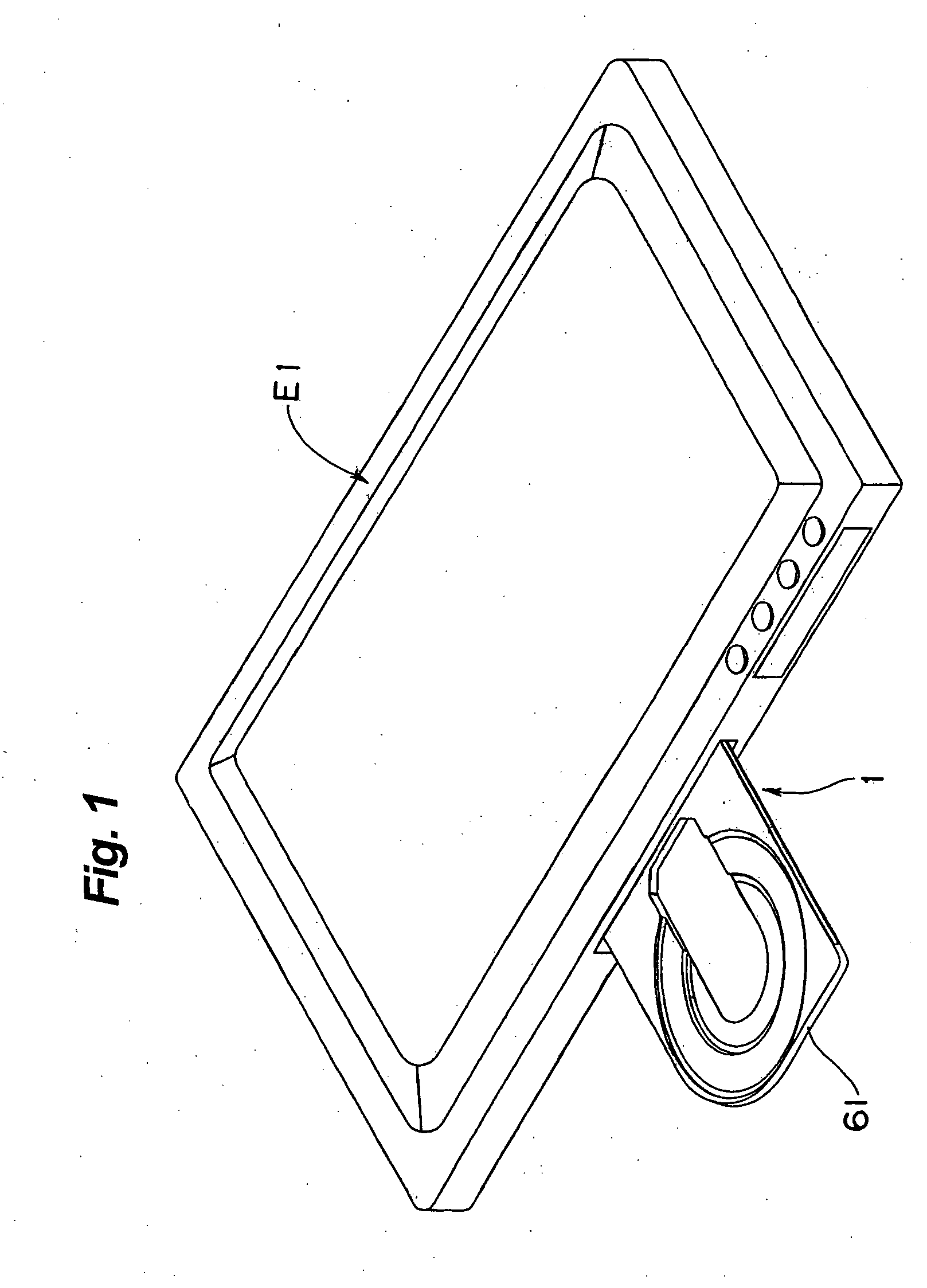
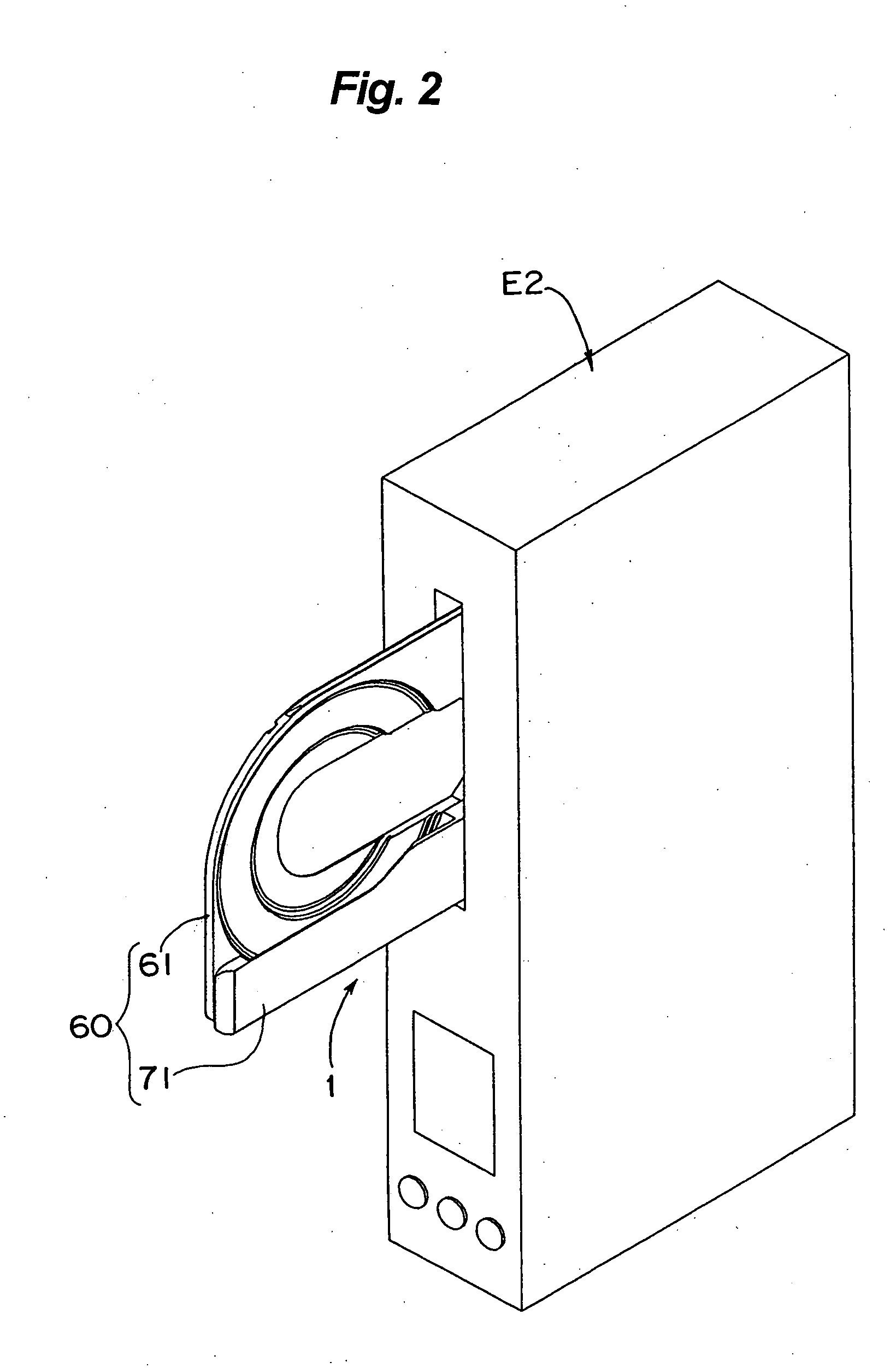
[0078] Hereinafter, one preferred embodiment of the present invention will be described in more detail referring to the accompanying drawings. FIGS. 1 and 2 are perspective views of disk loading apparatuses E1 and E2 (e.g. personal computers) respectively which are loaded with so-called CDs or DVDs as data recording mediums. FIG. 1 illustrates a personal computer E1 of so-called horizontal type with a disk loaded in a substantially horizontal position. FIG. 2 illustrates a personal computer E2 of so-called vertical type with a disk loaded in a substantially vertical position. FIG. 3 is an enlarged perspective view showing a disk 3 held in disk trays 61 and 71 (a tray unit 60) which are drawn out from the vertical type personal computer E2.

[0079] Each of the personal computers E1 and E2 includes a disk drive 1 employing a disk transfer device of the present invention. The disk drive 1 is applicable to either the horizontal type personal computer E1 or the vertical type personal comp...


PUM

PropertyMeasurementUnit
diameteraaaaaaaaaa
diameteraaaaaaaaaa
anglesaaaaaaaaaa

Abstract

The disk transfer device according to the present invention includes a disk tray for holding the disk during the disk transfer action and a tray driving mechanism for driving the tray forward and backward between a first position which is the retracted location of the tray corresponding to a turn table in a disk drive and a second position which is the loading and unloading location of the disk outwardly of the disk drive, wherein the disk tray comprises a main tray for supporting one side of the disk and a sub tray provided separately of the main tray for holding the other side of the disk, the main tray and the sub tray are joined to each other to have a pocket for accommodating partially the disk.

Description

TECHNICAL FIELD [0001] The present invention relates to a disk transfer device to be used in a disk drive for recording a data signal and / or reproducing a data signal recorded to a disk used as a data storage medium such as so-called a CD (Compact Disk) or so-called a DVD (Digital Video Disk or Digital Versatile Disk). BACKGROUND ART [0002] Conventionally, as a disk transfer device to be used in the above-mentioned disk drive, a disk transfer device to be used in a disk loading equipment that has an opening on the front panel through which a disk tray is drawn out or retracted is well known. In this case, after the tray is drawn out from the disk loading equipment and a disk is loaded onto the tray, the tray is automatically retracted into a predetermined position (a mounted position onto the turntable) in the disk drive assembled in the loading equipment. [0003] In such a type of disk drive, when a disk on the tray is retracted into the disk drive, it is held between the turntable ...

Claims


Application Information

Patent Timeline
Patent Type & Authority Applications(United States)
IPC IPC(8): G11B17/04
CPCG11B17/056
Inventor ARIYOSHI, YUJIATAGUCHI, OSAMUNODA, YOSUKE
Owner PANASONIC CORP
Why Eureka
Try Eureka