Suction head for vacuum cleaner

a vacuum cleaner and suction head technology, applied in the direction of vacuum cleaners, cleaning equipment, domestic applications, etc., can solve the problems of shortening the life inconvenient cleaning of the suction head b>2/b>, and failure of the vacuum cleaner, so as to facilitate the cleaning

Inactive Publication Date: 2005-06-16
KWANG DONG HITECH
View PDF0 Cites 8 Cited by
  • Summary
  • Abstract
  • Description
  • Claims
  • Application Information

AI Technical Summary

Benefits of technology

[0013] The present invention is designed in consideration of such problems, and therefore an object of the invention is to provide a suction head for a vacuum cleaner, which prevents a stuff to be cleaned from being sucked into a suction hole when a user cleans a flexible stuff such as sheet, carpet and curtain, thereby facilitating easy cleaning.

Problems solved by technology

However, this suction head 2 may be inconvenient for cleaning depending on a place to be cleaned.
In addition, if the suction hole 2a of the suction head 2 is clogged by the stuff L, the vacuum motor is overloaded to cause a failure of the vacuum cleaner.
However, this vacuum cleaner requires additional components such as motor and belt to drive the cylindrical roller, and these components are continuously operated while the vacuum cleaner is operating whether a user wants to do or not, thereby shortening the life of the vacuum cleaner.
Thus, when cleaning a hard place such as a floor, the hitting member protruded a predetermined length is continuously rotated to generate serious noise.
In addition, since the turbine keeps operating when the motor in the cleaner body is driven, a user cannot selectively operate the turbine.
However, since the turbine is always operated when the vacuum cleaner is operating, the dust brushing protrusions generate noise when a user cleans floor of parlor or room and the user may not selectively operate the shaking member as desired, as mentioned above.
However, this vacuum cleaner requires a driving means such as belt and gear for transferring a rotating force of the turbine, increasing production costs.
In addition, since the turbine is always operated when the vacuum cleaner is turned on, the protruded members cause noise when a user cleans floor of parlor or room, and the user may not selectively operate the protruded members as necessary.

Method used


Image

  • Suction head for vacuum cleaner
  • Suction head for vacuum cleaner
  • Suction head for vacuum cleaner

Examples


Embodiment Construction

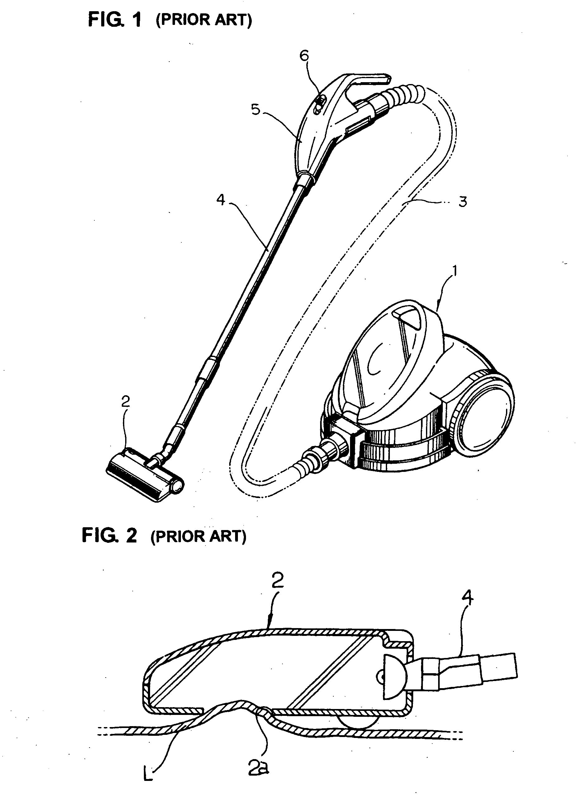
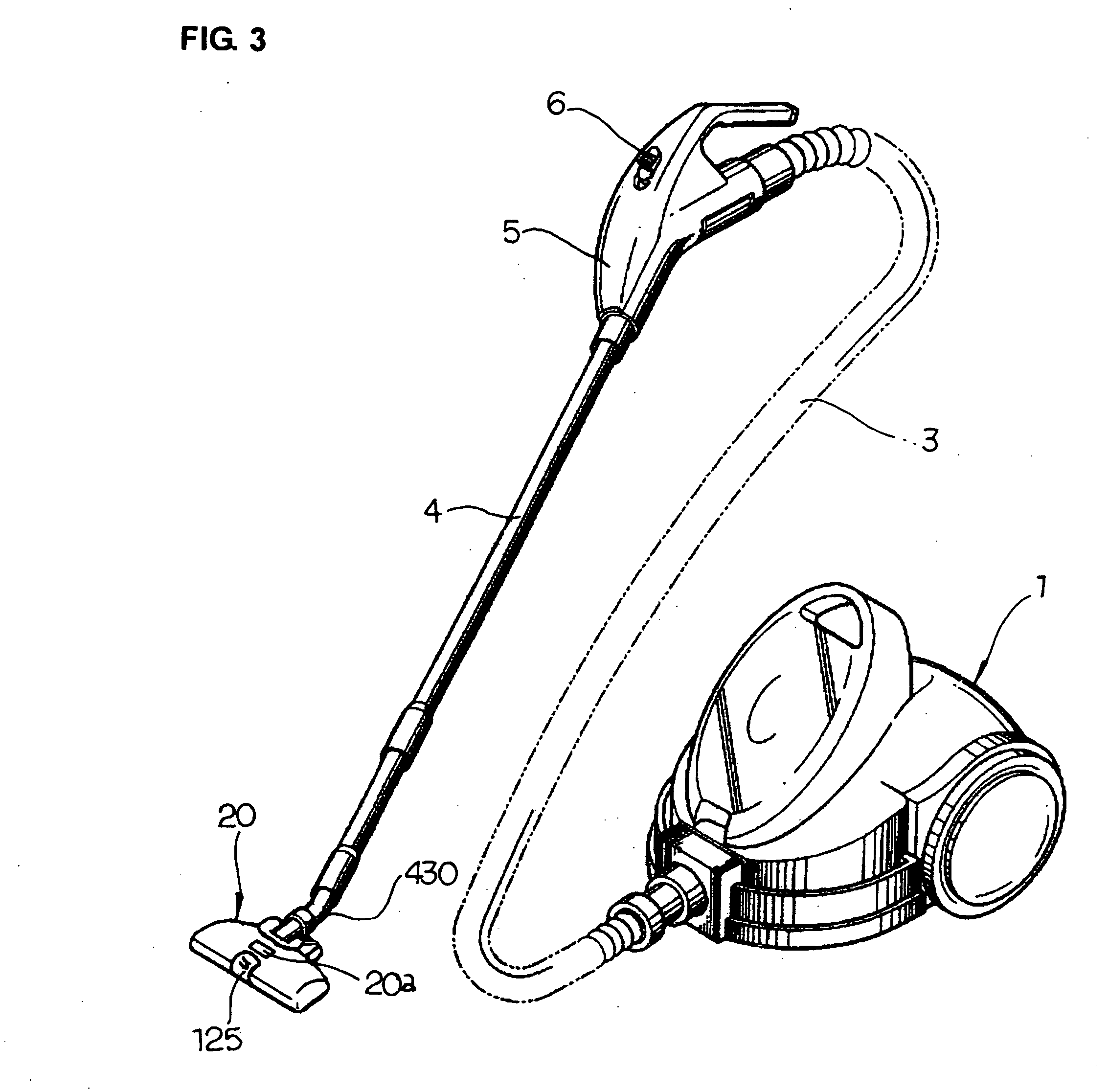
[0029]FIG. 3 is a perspective view showing a vacuum cleaner equipped with a suction head according to the present invention, in which the same reference numeral as shown in FIG. 1 designates the same component and it is not described in detail here.

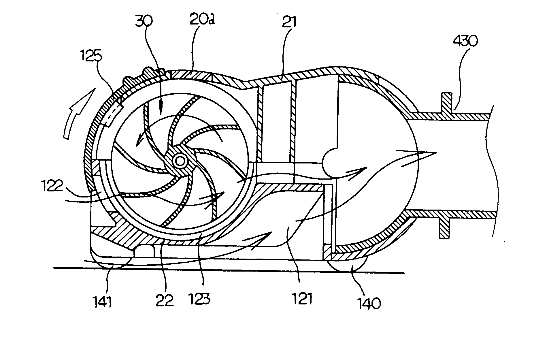
[0030] As shown in FIG. 3, the suction head according to the present invention includes a main body 20, and the main body 20 includes upper and lower cases 21 and 22 combined in contact with each other. A connection member 430 communicated with the main body 1 of the vacuum cleaner is mounted to one side of the suction head, and a suction hole 121 is formed in the lower case 22 adjacent to the connection member 430.

[0031] In addition, an air introduction hole 122 is formed in front of the suction hole 121 so as to selectively operate a turbine 30 and control a rotating speed of the turbine 30, and a turbine container 123 and a plurality of sliding holes 124 are formed between the air introduction hole 122 and the suction hole 121. As we...


PUM


Abstract

A suction head for a vacuum cleaner includes a main body and a connection member mounted in communication with a vacuum cleaner. The main body includes a suction hole adjacent to the connection member, and an air introduction hole in front of the suction hole so as to selectively operate and control a speed of a turbine. A turbine container and a plurality of sliding holes are formed between the air introduction hole and the suction hole; The turbine is received in the turbine container so as to be rotated only when the air introduction hole is open. A plurality of hitting members are slidably mounted in the main body. A pressing member extends from both ends of the turbine. The pressing member rotates together with the turbine to press the hitting members in the sliding holes, causing the hitting members hit a stuff to be cleaned.

Description

BACKGROUND OF THE INVENTION [0001] The present invention relates to a suction head for a vacuum cleaner, and more particularly to a suction head for a vacuum cleaner having a bedclothes dust brushing function for hitting bedclothes such as a carpet with one suction head to brush away impurities such as dust adhered thereto, and a general cleaning function for cleaning hard stuffs such as floor or parlor or room. [0002] Generally, a vacuum cleaner includes a main body 1 including such as a motor for generating suction force, a suction head 2 for sucking such as dusts on the floor by means of the suction force from the main body 1, and a flexible hose 3 and an extension pipe 4 for connecting the main body 1 and the suction head 2, as shown in FIG. 1. [0003] Thus, if a user manipulates a switch 6 installed to a handle 5 to operate the vacuum cleaner, the motor in the main body 1 is driven to conduct suction. Accordingly, dusts are sucked through a suction hole 2a formed on the bottom o...

Claims


Application Information

Patent Timeline
Patent Type & Authority Applications(United States)
IPC IPC(8): A47L9/02A47L9/04
CPCA47L9/0416A47L9/04
Inventor SONG, YONG-GON
Owner KWANG DONG HITECH
Why Eureka
Try Eureka