
Contactless identification tag, data communication system and contactless identification tag control program

Inactive Publication Date: 2005-06-16
SEIKO EPSON CORP
View PDF6 Cites 32 Cited by
  • Summary
  • Abstract
  • Description
  • Claims
  • Application Information

AI Technical Summary

Benefits of technology

[0013] It is further noted that, in accordance with the present invention, block dividing methods may be enumerated including a method to divide a bit string indicating an identification number into blocks in units of a predetermined numbers of bits in a state in which each of the blocks does not have any bit overlapping with the other blocks; a method to divide it into blocks in units of a predetermined numbers of bits in a state in which each of the blocks does not have any bit overlapping with the other blocks, and adjacent ones of the blocks are spaced from each other by a predetermined number of bits; and a method to divide it into blocks in units of a predetermined numbers of bits in a state in which each of the blocks has bits partially overlapping with the other blocks, and the like If the block division is done in a manner that adjacent ones of the blocks partially overlap one another, as mentioned above, the number of blocks to be divided can be increased, and therefore the probability that time slot numbers become duplicate among a plurality of contactless identification tags can be reduced.
[0016] According to this embodiment, the contactless identification tag does not uniquely decide a time slot number with a random number generated by the random number generation means, but can decide and set a time slot number based on the random number and the identification number, such that a time slot number that does not depend only on the event probability of number generation of the random number generation means can be set, and therefore a time slot number setting process that is difficult to duplicate numbers among a plurality of contactless identification tags can be performed.
[0027] Accordingly, unnecessary communication between the reader / writer device and the contactless identification tags can be prevented, and a condition where time slot numbers are not duplicated among a plurality of contactless identification tags can be quickly established.
[0035] Compared with other embodiments of the invention, even if time slot numbers are duplicate, there is no need to transmit information concerning the duplication from the reader / writer device to the host device. Moreover, there is no need to give an instruction to reset time slot numbers from the host device to the reader / writer device. Accordingly, the present invention contributes to shortening the time for communications between the host device and the reader / writer device.
[0037] In another embodiment of the invention, the host device is equipped with tag information display means for displaying the tag information obtained from the reader / writer device. With such a structure, the host device can display, with the tag information display means, the tag information obtained from the reader / writer device. Accordingly, an administrator that manages the host device can readily acquire tag information, and can appropriately operate the host device.
[0040] With such a structure, the reader / writer device can give, with the operation suspension instruction means, an instruction to the contactless identification tags to suspend their operation, and can give, with the operation restart instruction means, an instruction to the contactless identification tags whose operation is suspended by the operation suspension instruction means, to restart their operation. Accordingly, unnecessary communications between the reader / writer device and the contactless identification tags can be prevented, and a condition where time slot numbers are not duplicated among a plurality of contactless identification tags can be quickly established.

Problems solved by technology

As a result, there are possibilities that interferences may be caused many times, and it may take a long time to cancel the interferences.

Method used


Image

  • Contactless identification tag, data communication system and contactless identification tag control program
  • Contactless identification tag, data communication system and contactless identification tag control program
  • Contactless identification tag, data communication system and contactless identification tag control program

Examples


first embodiment

(1) FIRST EMBODIMENT

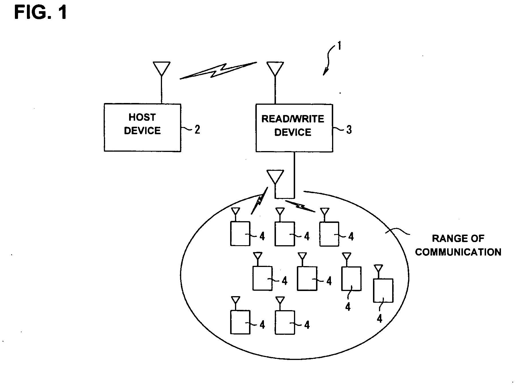
[0062] First, the structure of a data communication system in accordance with the present invention is described with reference to FIG. 1. FIG. 1 shows a diagram indicating the overall structure of the data communication system in accordance with the present invention.

[0063] The data communication system 1 has a structure including, as shown in FIG. 1, a host device 2, a reader / writer device 3, and a plurality of contactless identification tags 4. The host device 2 has a function to transmit various commands through the reader / writer device 3 to the contactless identification tags 4, and a function to manage various information about the contactless identification tags 4 within the range of communication of the reader / writer device 2. Their detailed structures are described below.

[0064] The reader / writer device 3 has a function to perform data communications in a contactless manner between a plurality of contactless identification tags 4 in the range of communi...

second embodiment

(2) SECOND EMBODIMENT

[0153]FIG. 9 is a time chart indicating the process flows of the respective devices at the time of setting time slot numbers in the data communication system 1. Here, although not particularly shown in the figure, it is assumed that four (first through fourth) contactless identification tags 4A-4D (Tag 1-Tag 4 in FIG. 9, respectively) are present in the range of communication of the reader / writer device 3.

[0154] Also, as a unique identification number (UID), “0010-1101-0000” is set in the first contactless identification tag 4A, “1110-0001-1101” is set in the second contactless identification tag 4B, “0010-0000-1011” is set in the third contactless identification tag 4C, and “0000-1010-1111” is set in the fourth contactless identification tag 4D, respectively. Here, the identification number is divided by “-” signs into three blocks, each having a bit string of four digits as one block.

[0155] First, the host device 2 transmits to the reader / writer device 3 a c...


PUM


Abstract

A data communication system includes a host device, a reader / writer device and a plurality of contactless identification tags. The contactless identification tag includes a data reception section, a data transmission section, a data control section, a data storage section, a driving electric current generation section and a coil antenna. In response to a command from the reader / writer device, the data control section generates a random number, and sets a time slot number based on the random number and a unique identification number stored in advance in the data storage section.

Description

BACKGROUND OF THE INVENTION [0001] 1. Field of the Invention [0002] The present invention relates to contactless radio data communications that use contactless identification tags and a reader / writer device, and more particularly, to contactless identification tags, data communication systems and contactless identification tag control programs, which are suitable for setting the sequence of communications when a plurality of contactless identification tags are present in the range of communication of a reader / writer device. [0003] 2. Description of Related Art [0004] Japanese Patent Document 2814974 describes contactless IC cards and a data communication device, as a data communication technology which sets an appropriate sequence of communications for a reader / writer device and a plurality of RF-ID tags. When the reader / writer device disclosed in Japanese Patent Document 2814974 communicates with a contactless IC card via radio communications, and confirms an interference at an ini...

Claims


Application Information

Patent Timeline
IPC IPC(8): G06K19/07G06K7/00G06K17/00H04B1/59H04B5/02
CPCG06K7/10039G06K7/0008
Inventor MATSUMOTO, KENJIASO, SATOSHI
Owner SEIKO EPSON CORP
Learn More