Temperature compensation for a variable frequency oscillator without reducing pull range

a variable frequency oscillator and temperature compensation technology, applied in oscillator generators, pulse automatic control, electrical equipment, etc., can solve problems such as the frequency pulling effect of resonators

Inactive Publication Date: 2005-06-16
SEIKO EPSON CORP
View PDF12 Cites 43 Cited by
  • Summary
  • Abstract
  • Description
  • Claims
  • Application Information

AI Technical Summary

Benefits of technology

[0022] Generally, the variable oscillator consists of a resonant circuit, a gain stage, and a phase shift network. The gain stage and phase shift network may be combined, if desired. Preferably, the resonant circuit include a resonator, such as a quartz crystal, inductor, capacitor, or tank circuit, and further includes mul

Problems solved by technology

The tuning circuits are connected in parallel to each other and to the resonator, such that adjusti

Method used


Image

  • Temperature compensation for a variable frequency oscillator without reducing pull range
  • Temperature compensation for a variable frequency oscillator without reducing pull range
  • Temperature compensation for a variable frequency oscillator without reducing pull range

Examples


Embodiment Construction

[0046] Preferred embodiments of the present invention are described below with reference to the accompanying figures, where like elements are identified with common reference characters.

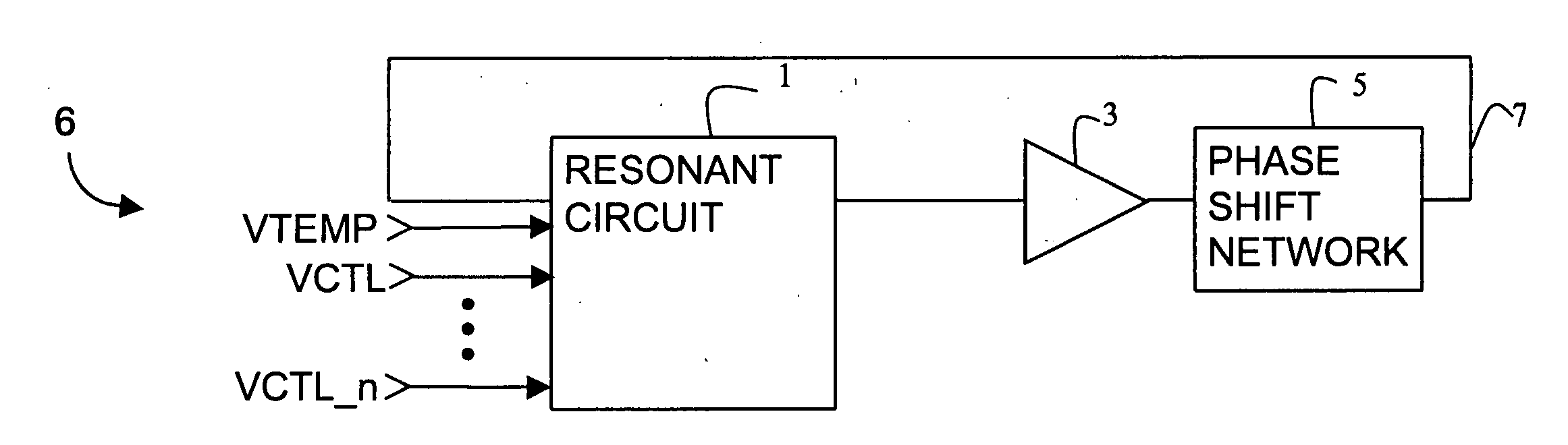
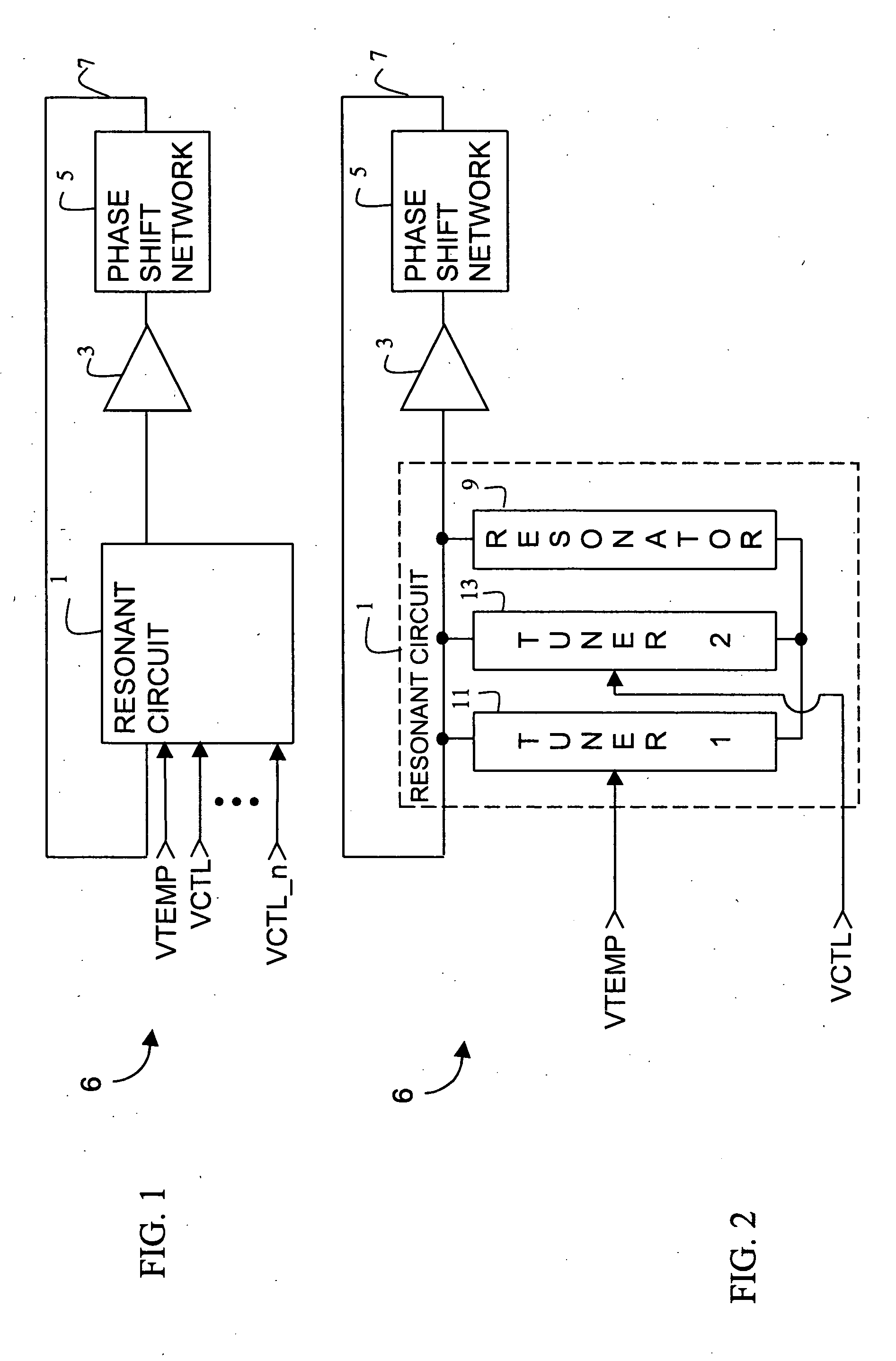
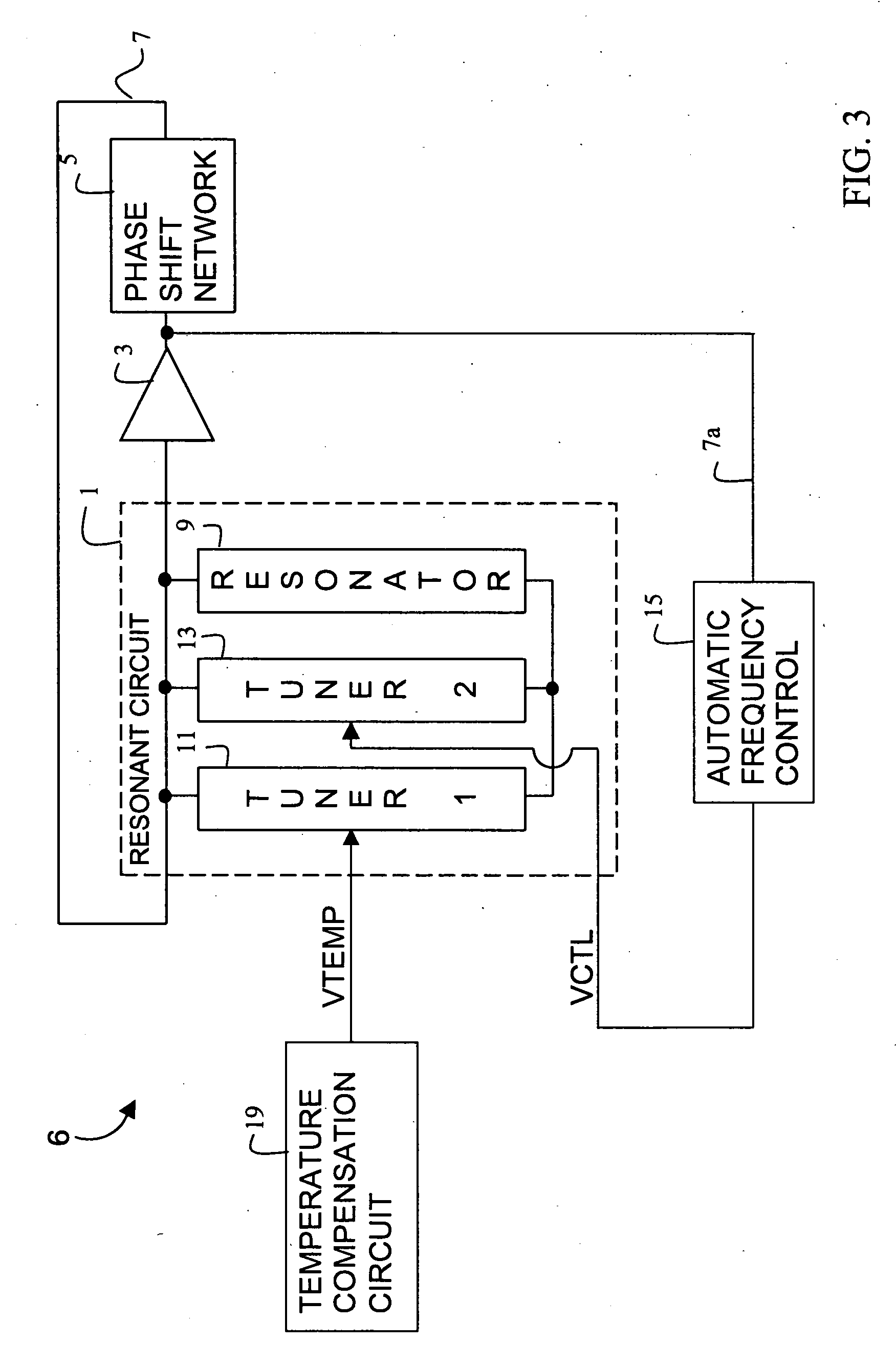
[0047] With reference to FIG. 1, a variable oscillator 6 in accord with the present invention includes a resonant circuit 1 having multiple frequency control inputs VTEMP and VCTL through VCTL_n. As is typical of oscillators, oscillator 6 preferably additionally includes an amplifying stage 3 and a phase shift network 5 in a feedback loop around resonant circuit 1.

[0048] In the present case, resonant circuit 1 has a single temperature compensation control input VTEMP and multiple functional frequency control inputs VCTL through VCTL_n. Each frequency control input VTEMP and VCTL through VCTL_n is independent of each other and thus all can provide active frequency control concurrently, and each has an independent control range such that the control range of any one control input is not reduced by th...


PUM


Abstract

A variable frequency oscillator having multiple, independent frequency control inputs, each coupled to a respective tuning sub-circuit. The tuning sub-circuits are connected in parallel with each other and with a resonator module, which may be a quartz crystal, inductor, or other reactance component. Each tuning sub-circuit consists of two varactors with their respective cathodes coupled to each other and to their corresponding frequency control input. By having the tuning sub-circuits connected in parallel to the resonator, the overall frequency pull range of each frequency control input remains unaffected by the activation of any other frequency control input. Preferably, at least one frequency control input is a temperature compensation control input that can maintain the variable oscillator insensitive to temperature variations while the remaining frequency control inputs provide functional frequency control.

Description

BACKGROUND OF THE INVENTION [0001] 1. Field of the Invention [0002] The present invention relates generally to variable frequency oscillators and in particular to variable frequency oscillators which must maintain a particular frequency of oscillation despite temperature variations. The present invention further relates to oscillators that must provide sufficient frequency pull range to respond to both frequency compensation circuitry and to frequency correction signals due to normal circuit operations. [0003] 2. Description of the Related Art [0004] Voltage or current controlled variable frequency oscillators are frequently used in precision clock generators for digital systems. Such variable oscillators have a frequency control input that permits the oscillator's frequency to be modified in accordance with a frequency control signal. However, the oscillator's operating range for responding to the frequency control signal is limited, if not by the particular architecture of the osc...

Claims


Application Information

Patent Timeline
IPC IPC(8): H03B5/04H03B5/32H03B5/08H03B5/12H03L1/02H03L7/00
CPCH03B5/04H03L1/022Y10S331/03H03L7/00H03L1/023
Inventor MELTZER, DAVID
Owner SEIKO EPSON CORP
Why Eureka
Try Eureka