
VTV system

a vtv system and image technology, applied in television systems, selective content distribution, instruments, etc., can solve the problems of complex conventional systems for producing three-dimensional images, inability to allow users to control the viewing direction and relative position of viewers, and high cost of media graphics to be generated, so as to enhance the spatial television-like viewing experience

Active Publication Date: 2005-06-16
RICHARDS ANGUS
View PDF5 Cites 52 Cited by
  • Summary
  • Abstract
  • Description
  • Claims
  • Application Information

AI Technical Summary

Benefits of technology

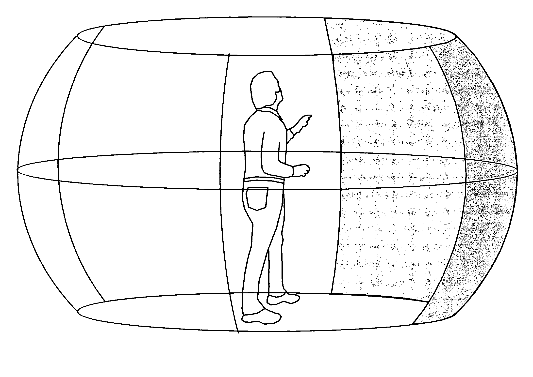
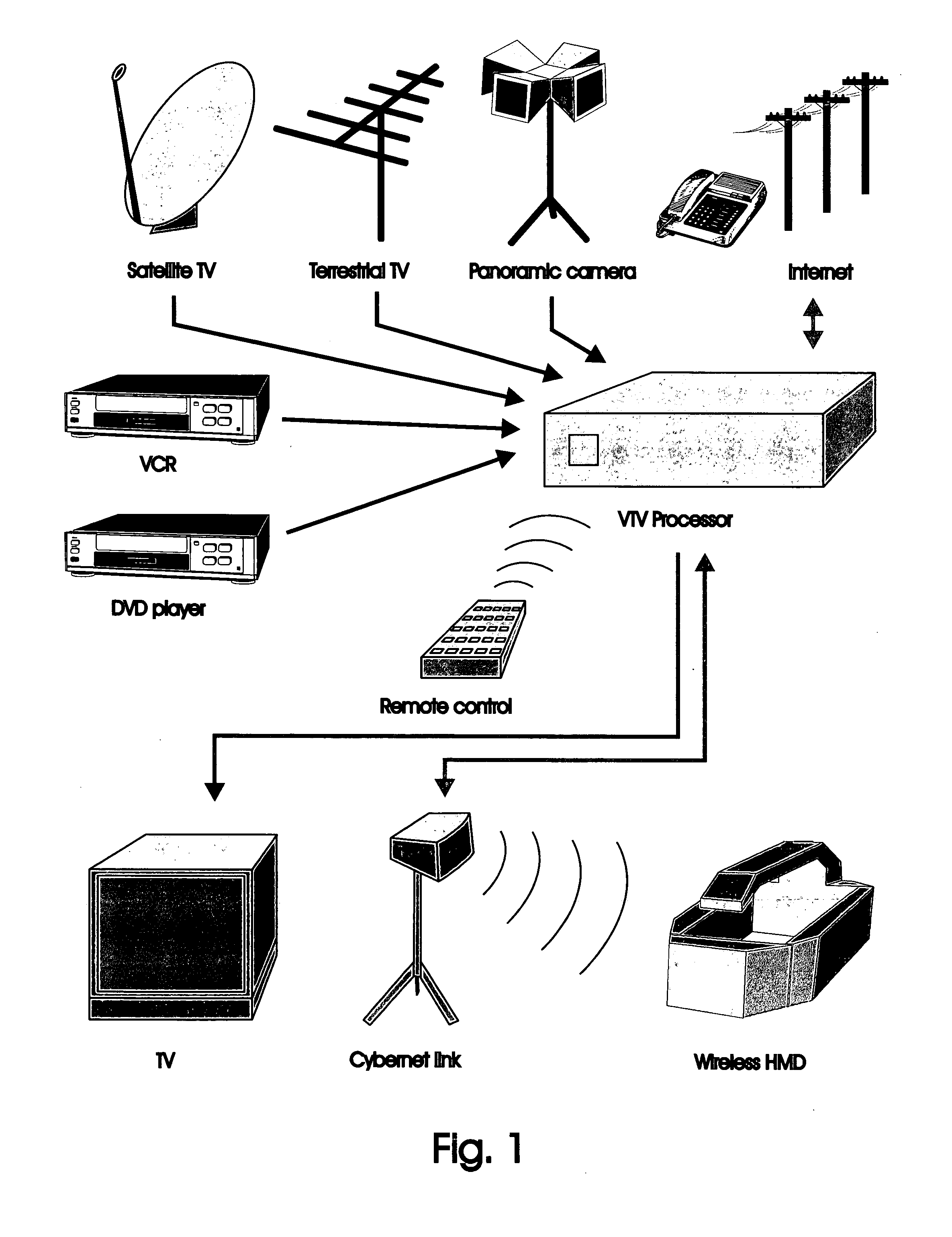
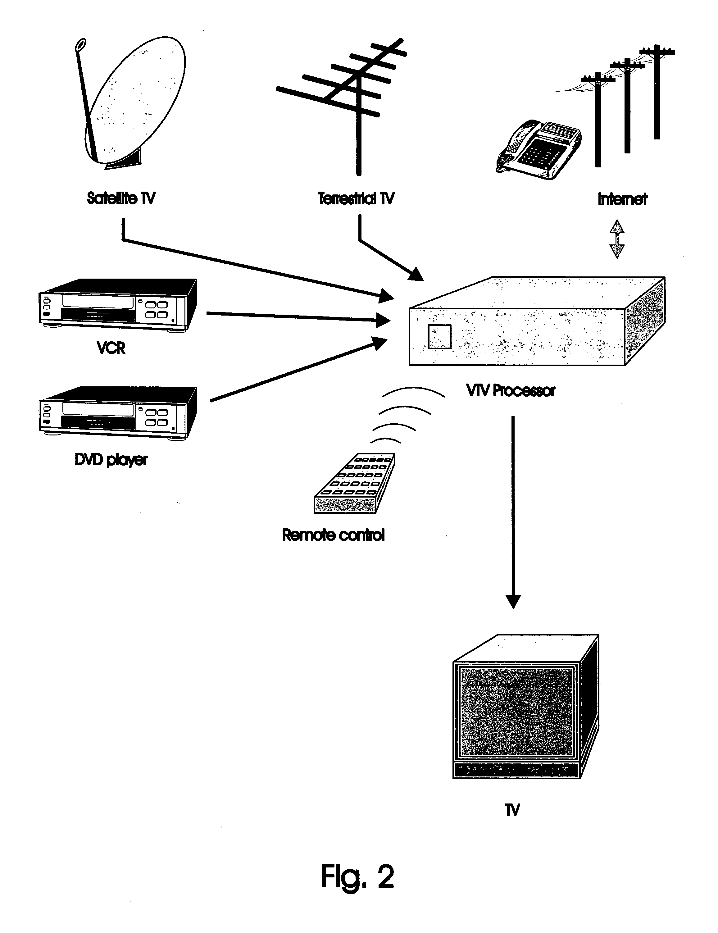
[0004] The following invention relates to an overall hardware configuration that produces an enhanced spatial television-like viewing experience. Unlike normal television, with this system the viewer is able to control both the viewing direction and relative position of the viewer with respect to the movie action. In addition to a specific hardware configuration, this invention also relates to a new video format which makes possible this virtual reality like experience. Additionally, several proprietary video compression standards are also defined which facilitate this goal. The VTV system is designed to be an intermediary technology between conventional two-dimensional cinematography and true virtual reality.

Problems solved by technology

While normal televsion or movie screens are a common form of modern entertainment, these conventional systems do not allow a user to control the viewing direction and relative position of the viewer with respect to the movie action.
Additionally, while virtual reality viewing is becoming increasingly popular, conventional systems for producing three dimensional images are often complex and the media graphics are costly to generate.

Method used


Image

  • VTV system
  • VTV system
  • VTV system

Examples


Embodiment Construction

[0029] The detailed description set forth below in connection with the appended drawings is intended as a description of presently-preferred embodiments of the invention and is not intended to represent the only forms in which the present invention may be constructed and / or utilized. The description sets forth the functions and the sequence of steps for constructing and operating the invention in connection with the illustrated embodiments. However, it is to be understood that the same or equivalent functions and sequences may be accomplished by different embodiments that are also intended to be encompassed within the spirit and scope of the invention.

[0030] 1.1) The following patent relates to an overall hardware configuration that produces an enhanced spatial television-like viewing experience. Unlike normal television, with this system the viewer is able to control both the viewing direction and relative position of the viewer with respect to the movie action. In addition to a s...


PUM


Abstract

An electronic system that produces an enhanced spatial television-like audio-visual experience is disclosed. Unlike normal television, the system enables the viewer to control both the viewing direction and relative position of the viewpoint with respect to the movie action. In addition to a specific hardware configuration, this patent also relates to a new video format which makes possible this virtual reality like experience including a system by which multi-channel audio can be recorded in addition to visual information onto a single data channel which is compatible with existing television and audio-visual standards and an optical tracking system to provide both angular and spatial position information to control the display of said imagery and spatial audio.

Description

REFERENCE TO RELATED APPLICATION [0001] This application claims priority from U.S. utility application Ser. No. 09 / 891,733 entitled “VTV System” filed Jun. 25, 2001 by Angus Duncan Richards.TECHNICAL FIELD [0002] This invention relates to image viewing and sound systems. BACKGROUND ART [0003] While normal televsion or movie screens are a common form of modern entertainment, these conventional systems do not allow a user to control the viewing direction and relative position of the viewer with respect to the movie action. Additionally, while virtual reality viewing is becoming increasingly popular, conventional systems for producing three dimensional images are often complex and the media graphics are costly to generate. DISCLOSURE OF INVENTION [0004] The following invention relates to an overall hardware configuration that produces an enhanced spatial television-like viewing experience. Unlike normal television, with this system the viewer is able to control both the viewing directi...

Claims


Application Information

Patent Timeline
IPC IPC(8): G06F3/048H04N5/272H04N5/60H04N5/74
CPCG06F3/04815H04N21/8106H04N5/602H04N5/607H04N9/3147H04N21/23614H04N21/2368H04N21/242H04N21/4223H04N21/42653H04N21/4305H04N21/4307H04N21/431H04N21/4341H04N21/4348H04N21/44218H04N5/272H04N21/43072
Inventor RICHARDS, ANGUS
Owner RICHARDS ANGUS
Learn More