
Real-image finder optical system

a real-image finder and optical system technology, applied in the field of real-image finder optical system, can solve the problems of inconvenient use, shortening the focal length of the objective optical system, and increasing the thickness of the camera, so as to achieve long eye relief and high finder magnification

Inactive Publication Date: 2005-06-16
ASAHI KOGAKU KOGYO KK
View PDF30 Cites 2 Cited by
  • Summary
  • Abstract
  • Description
  • Claims
  • Application Information

AI Technical Summary

Benefits of technology

[0010] It is an object of the present invention to provide a small-sized real-image finder optical system which has a high finder magnification, and has a long eye relief.
[0011] Another object of the present invention is to provide a small-sized real-image finder optical system in which dust and scratches are not noticeable when an object is viewed through the finder optical system.

Problems solved by technology

Accordingly, the thickness (length from front to back) of a camera, which is necessary to incorporate such an optical system, is undesirably increased.
However, if a further attempt is made to reduce the length of the real-image finder optical system of this type in the front-to-back direction, there is a need to shorten the focal length of the objective optical system, since the objective optical system occupies the majority of the overall length of the finder optical system.
Consequently, the eye relief becomes shorter, so that ease for viewing may not properly be secured.
Still further, the focal length of the objective optical system becomes excessively short with respect to the focal length of the eyepiece lens element (eyepiece optical system), thereby the finder magnification (fo / fe; fo: the focal length of the objective optical system; fe: the focal length of the eyepiece lens element (eyepiece optical system)) decreases, and it becomes difficult for an operator to view an object image, and the quality of the object image may deteriorate.
However, in a conventional real-image finder optical system, dust and scratches on the surface of the transparent member would also appear with the object image.
Particularly, in the case where the focal length of the eyepiece optical system is set to be short, such dust and scratches are enlarged, which may obstruct the field of view.

Method used


Image

  • Real-image finder optical system
  • Real-image finder optical system
  • Real-image finder optical system

Examples


embodiment 1

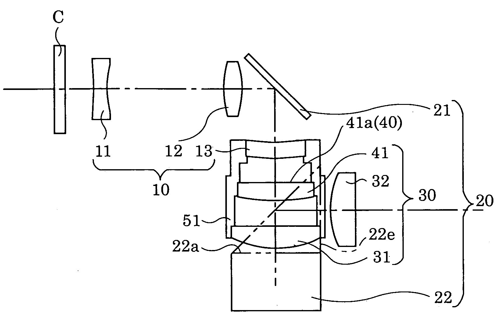
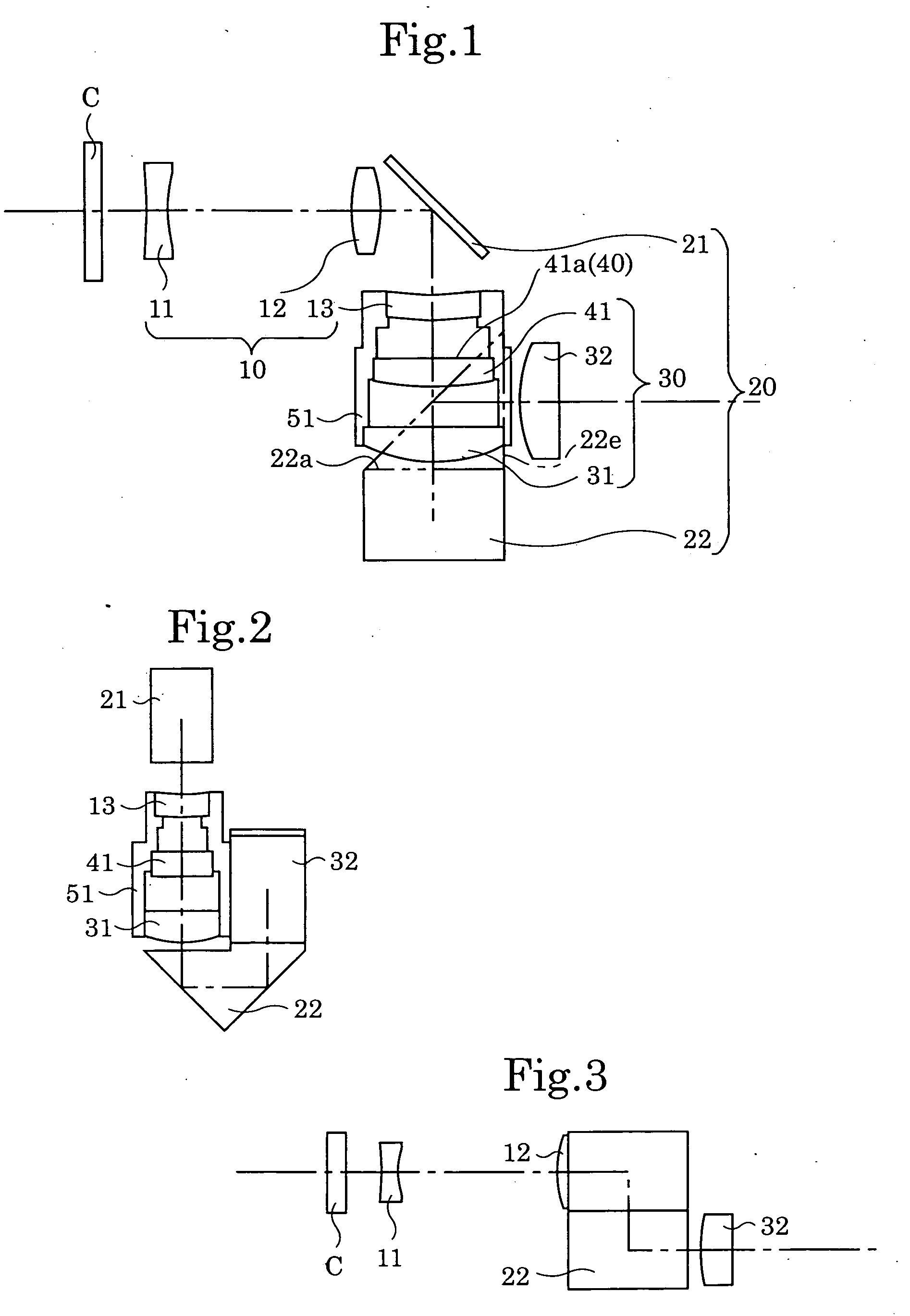
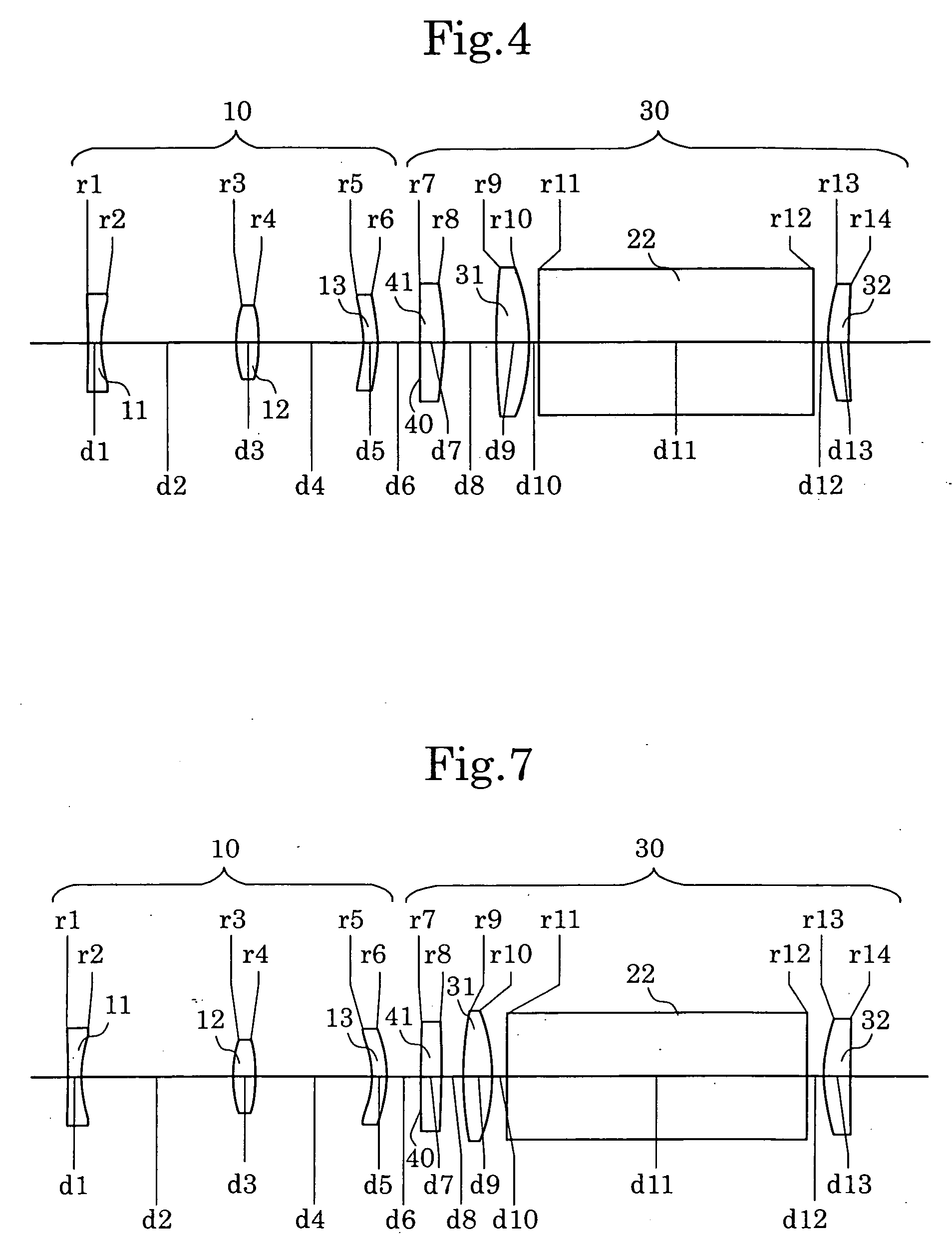
[0169]FIG. 1 is a plan view of the first embodiment of the real-image finder optical system. FIG. 2 is a rear view of FIG. 1. FIG. 3 is a side view of FIG. 1. FIG. 4 shows the optical arrangement of the real-image finder optical system, in which the reflection surfaces shown in FIGS. 1 to 3 are shown as developed views. FIGS. 5A through 5D show aberrations, at the short focal length extremity, occurred in the optical arrangement shown in FIG. 4. FIGS. 6A through 6D show aberrations, at the long focal length extremity, occurred in the optical arrangement shown in FIG. 4. Table 1 shows the numerical data of the first embodiment.

TABLE 1S.F.L.E. L.F.L.E.Finder Magnification (fo / fe)0.39-1.06Diopter [dptr] = −1.0Surface No.rdNdν 1*−29.4241.301.5854729.9 2*10.88013.49-2.620—— 3*8.0002.201.4917657.4 4−13.146 10.76-21.840—— 5*−16.0201.501.4917657.4 6−13.1134.30—— 7∞2.501.4917657.4 8−31.2405.46—— 962.2583.321.4917657.410*−12.6380.92——11∞28.001.4917657.412∞1.50——13*18.3452.501.4917657.414548...

embodiment 2

[0171]FIG. 7 shows the optical arrangement, according to the second embodiment, in which the reflection surfaces of a real-image finder optical system are shown as developed views. The optical arrangement of the second embodiment is the same as the first embodiment except that (i) surface Nos. 7 and 8 indicates a plane-parallel plate 41′, and (ii) the position where the object image by the objective optical system is formed is the eyepiece-side plane of the plane-parallel plate 41′, i.e., surface No. 8. FIGS. 8A through 8D show aberrations, at the short focal length extremity, occurred in the optical arrangement shown in FIG. 7. FIGS. 9A through 9D show aberrations, at the long focal length extremity, occurred in the optical arrangement shown in FIG. 7. Table 2 shows the numerical data of this embodiment.

TABLE 2S.F.L.E. L.F.L.E.Finder Magnification (fo / fe)0.39-1.06Diopter [dptr] = −1.0Surface No.rdNdν 1*−30.5801.301.5854729.9 210.95313.80-2.680—— 3*8.0612.101.4917657.4 4−13.422 10...

embodiment 3

[0173]FIG. 10 shows the optical arrangement according to the third embodiment, in which the reflection surfaces of a real-image finder optical system are shown as developed views. The optical arrangement of the third embodiment is the same as the first embodiment except that (i) the positive meniscus third lens element 13 (surface Nos. 5 and 6) is replaced with a negative meniscus lens element having a concave surface facing towards the object, (ii) the eyepiece-side surface (No. 8) of the planoconvex lens element 41 (condenser lens: surfaces Nos. 7 and 8) is the flat surface, and (iii) the position where the object image by the objective optical system is formed is the eyepiece-side plane of the planoconvex lens element 41, i.e., surface No. 8. FIGS. 11A through 11D show aberrations, at the short focal length extremity, occurred in the optical arrangement shown in FIG. 10. FIGS. 12A through 12D show aberrations, at the long focal length extremity, occurred in the optical arrangemen...


PUM


Abstract

A real-image finder optical system includes a positive objective optical system, an erecting optical system, and a positive eyepiece optical system, thereby an object image, which is formed by the objective optical system, and is upside down and reversed from left to right, is reinverted by the erecting optical system to the proper orientation. The erecting optical system includes a plurality of reflection surfaces, at least one of which is provided along an optical path on the object side with respect to the position where the object image is formed, and at least another of which is provided along an optical path on the eyepiece side with respect to the position where the object image is formed. The eyepiece optical system includes a positive lens element having a transverse magnification of more than 1.0 provided between the object image (finder image) and the reflection surface provided on the eyepiece side with respect to the position where the object image is formed.

Description

CROSS-REFERENCE TO RELATED APPLICATION [0001] This application is a divisional of U.S. patent application Ser. No. 09 / 708,045, filed Nov. 8, 2000, the content of which is hereby incorporated herein by reference.BACKGROUND OF THE INVENTION [0002] 1. Field of the Invention [0003] The present invention relates to a real-image finder optical system applied to a camera in which the finder optical system is provided independently from the photographing optical system. [0004] 2. Description of the Related Art [0005] A real-image finder optical system is constituted by a positive objective optical system for forming an inverted object image which is upside down and reversed from left to right, an erecting optical system for erecting the inverted object image formed by the objective optical system to the proper orientation, and an eyepiece lens element (eyepiece optical system) for viewing the erected object image reinverted by the erecting optical system. In such a real-image finder optical...

Claims


Application Information

Patent Timeline
Patent Type & Authority Applications(United States)
IPC IPC(8): G02B23/14
CPCG02B13/10G02B23/14G02B17/0856
Inventor ABE, TETSUYA
Owner ASAHI KOGAKU KOGYO KK
Learn More