Systems, methods and devices relating to delivery of medical implants
Active Publication Date: 2005-06-16
BOSTON SCI SCIMED INC
View PDF100 Cites 147 Cited by
Summary
Abstract
Description
Claims
Application Information
AI Technical Summary
This helps you quickly interpret patents by identifying the three key elements:
Problems solved by technology
Method used
Benefits of technology
Benefits of technology
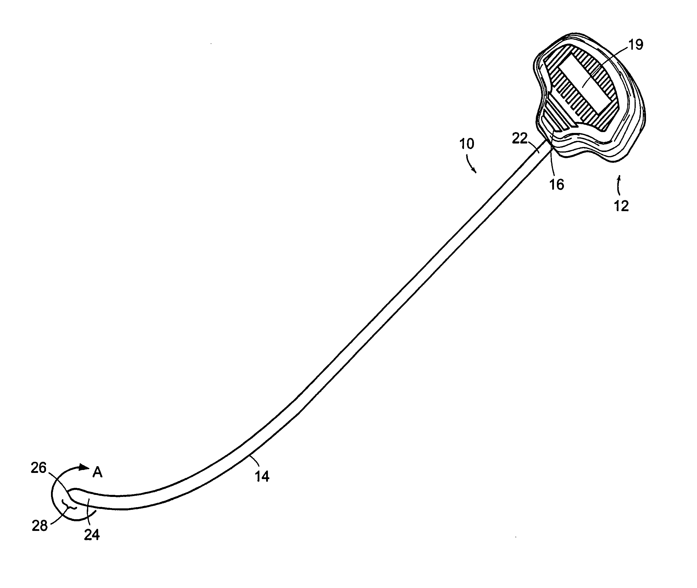
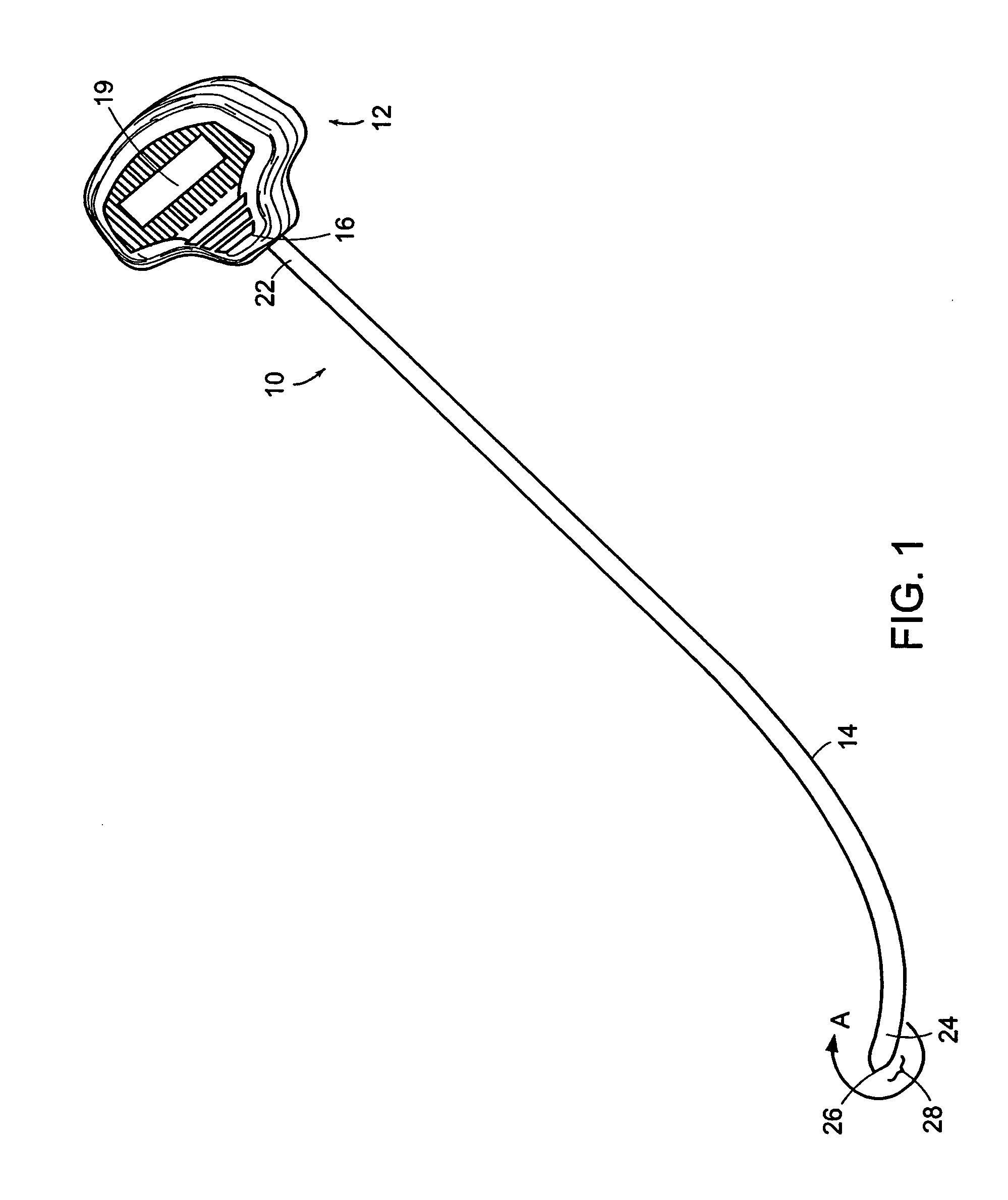
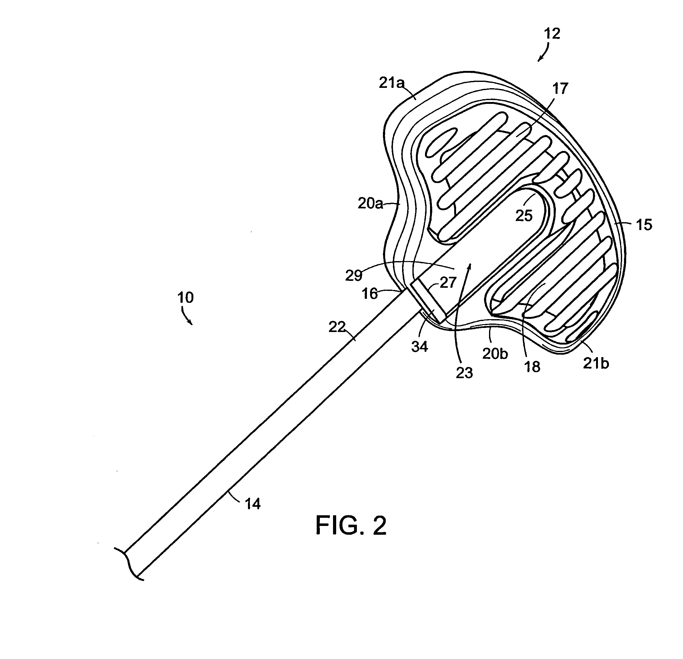
[0006] Accordingly, in one aspect, the invention features a connector pair for attaching a medical implant to a delivery device. The connector pair includes a closed loop connector located at an end of a medical implant, and a slotted connector formed in a distal end of a shaft of a delivery device for interfitting with the closed loop connector of the medical implant, the slotted connector including first and second legs, the first leg extending radially into the shaft and the second leg extending axially in a distal direction along the shaft.
[0007] The slotted connector can be configured to interfit with the closed loop connector. Alternatively, the closed loop connector can be configured to interfit into the first and/or second leg of the slotted connector. In one embodiment, the closed loop connector and the slotted connector are sized for end to end interconnection between the medical implant and the shaft of the delivery device.
[0008] The closed loop connector is preferably substantially rigid and can be formed from various materials such as a suturing material or semi-flexible, shape retaining material. Generally it is shaped to track the distal end of the shaft. In one embodiment, the closed loop connector includes a base portion, a tapered portion and a loop portion, the base portion extending from the end of the medical implant to the tapered portion, the tapered portion tapering radially outward and extending axially from the based portion to the loop portion, the loop portion being curved. In this embodiment, the distal end of the shaft is tapered for interfitting with the tapered portion of the closed loop connector.
[0009] In another embodiment, the slotted connector can include first and second channels located substantially diametrically opposi
Problems solved by technology
In ISD, the urinary sphincter valve, located within the urethra, fails to close properly (coapt), causing urine to leak out of the urethra during stressful activi
Method used
Image
Click on the blue label to locate the original text in one second.
Reading with bidirectional positioning of images and text.
Examples
Example
[0138] The invention relates to delivering and placing an implant, such as a sling, mesh, or suture, for the treatment of urinary incontinence, at an anatomical site (such as the periurethral tissue) in the body of a mammal. The patient may be either a female patient or a male patient.
[0139] The following description is divided into five sections. The first section, describes various illustrative delivery devices. The second section describes implants (such as sling assemblies) that may be delivered by, without limitation, any of the illustrative delivery devices. The third section describes connectors that may be used to interconnect two or more parts in an implant delivery system, such as, for example, interconnecting a sling assembly with a delivery device. The fourth section describes various illustrative methods for treatment of urinary incontinence, including illustrative embodiments that utilize components and systems described in this and the incorporated patents and patent...
PUM
Abstract
Implant delivery systems are disclosed. In general overview, an exemplary system includes any number of the following: a delivery device, a sling assembly, guide members, and connectors that interconnect the above. Embodiments of all the above components and their combinations are disclosed. Methods of using the above system in suprapubic, prepubic, transvaginal, trans-obturator and other approaches are also disclosed.
Description
CROSS REFERENCE TO RELATED APPLICATIONS [0001] This application is a continuation-in-part application of U.S. patent application Ser. Nos. 10 / 093,371, 10 / 093,398, 10 / 093,424, 10 / 093,450, 10 / 093,498, and 10 / 094,352 filed in the United States Patent Office on Mar. 7, 2002, which claim benefit of and priority to provisional patent application Ser. No. 60 / 274,843 filed in the United States Patent Office on Mar. 9, 2001 and provisional patent application Ser. No. 60 / 286,863 filed in the United States Patent Office on Apr. 26, 2001. The entire contents of these six nonprovisional applications are incorporated by reference herein. This application is also based on and claims priority to certain provisional U.S. patent applications, namely, Ser. No. 60 / 403,555 filed on Aug. 14, 2002, Ser. No. 60 / 418,827 filed on Oct. 15, 2002, Ser. No. 60 / 418,642, filed on Oct. 15, 2002, Ser. No. 60 / 434,167 filed on Dec. 17, 2002, Ser. No. 60 / 449,465 filed on Feb. 24, 2003, Ser. No. 60 / 465,722 filed on Apr....
Claims
Application Information
Patent Timeline
Application Date:The date an application was filed.
Publication Date:The date a patent or application was officially published.
First Publication Date:The earliest publication date of a patent with the same application number.
Issue Date:Publication date of the patent grant document.
PCT Entry Date:The Entry date of PCT National Phase.
Estimated Expiry Date:The statutory expiry date of a patent right according to the Patent Law, and it is the longest term of protection that the patent right can achieve without the termination of the patent right due to other reasons(Term extension factor has been taken into account ).
Invalid Date:Actual expiry date is based on effective date or publication date of legal transaction data of invalid patent.

