Flexible spinal fixation elements

Inactive Publication Date: 2005-06-16
DEPUY SYNTHES PROD INC
View PDF17 Cites 358 Cited by
  • Summary
  • Abstract
  • Description
  • Claims
  • Application Information

AI Technical Summary

Benefits of technology

[0005] The present invention generally provides a spinal fixation element that is formed from an elongate, bioimplantable member having at least two segments that are selectively movable with respect to one another. As a result, the elongate member is configurable in a first, flexible position, in which the segments are adapted to be

Problems solved by technology

The use of rigid, generally elongate spinal fixation elements, however, can be difficult to implant using minimally invasive techniques.
While this procedure offers advantages over prior art invasive techn

Method used


Image

  • Flexible spinal fixation elements
  • Flexible spinal fixation elements
  • Flexible spinal fixation elements

Examples


Embodiment Construction

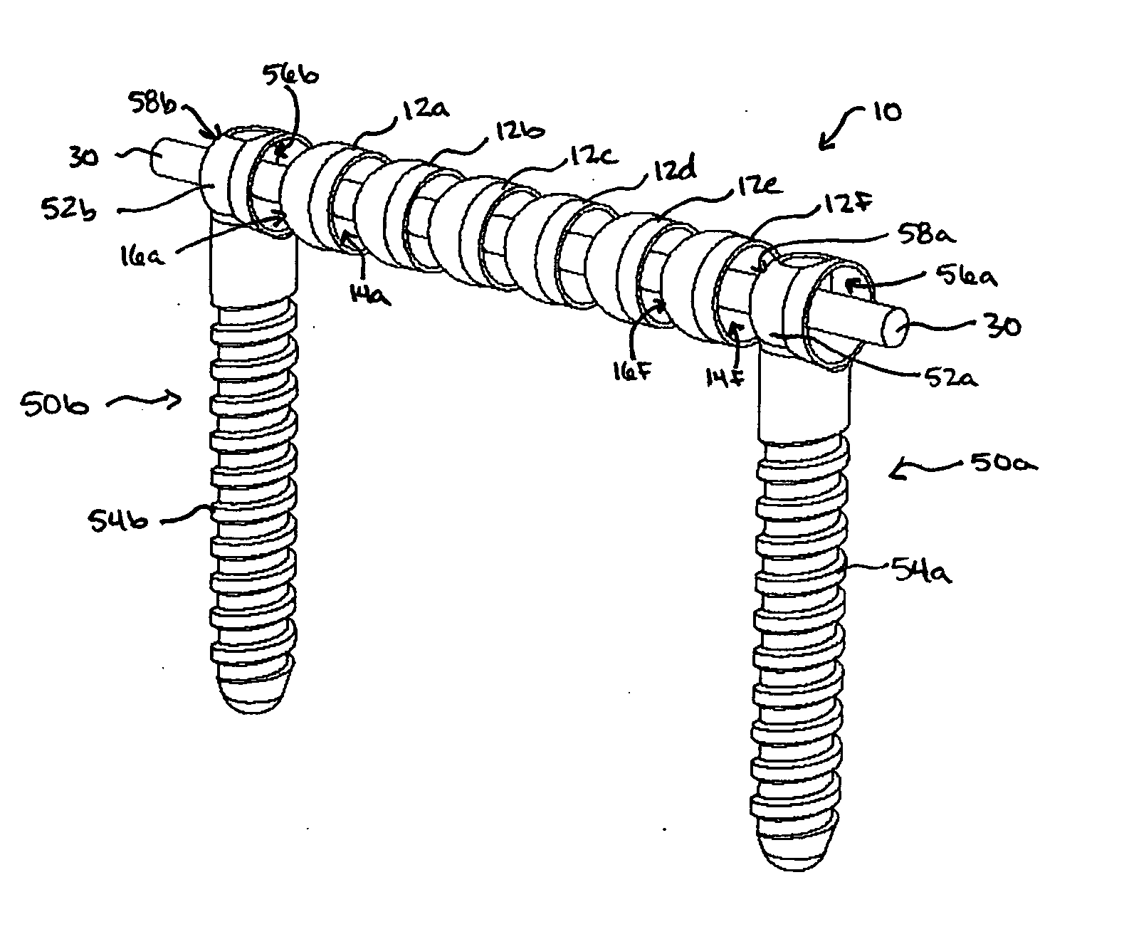
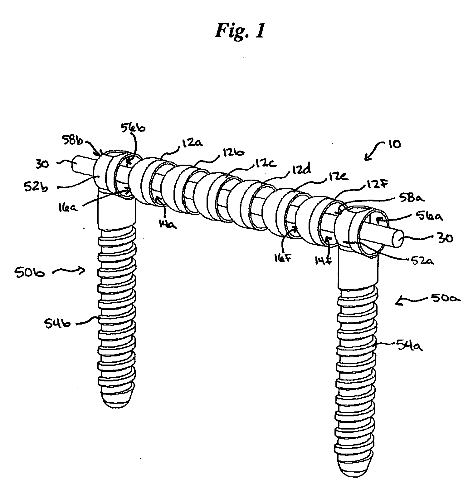
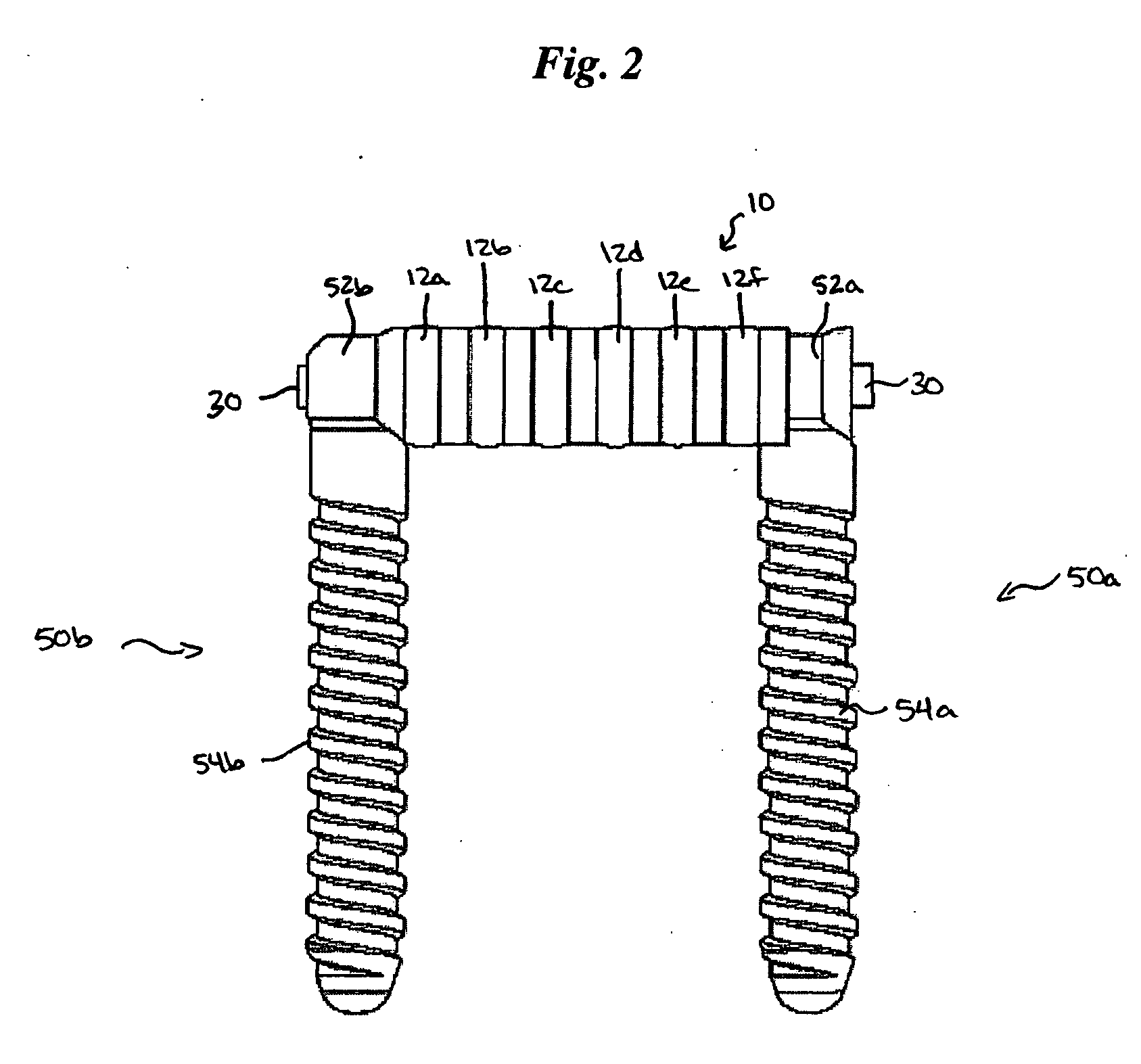
[0028] The present invention generally provides a spinal fixation element that is movable between a first position, in which the spinal fixation element is adapted to be angularly manipulated, and a second, locked position, in which the spinal fixation element is aligned in a desired orientation and is immovable. The configuration of the spinal fixation element can vary, but the fixation element is preferably formed from a bioimplantable member having segments or a bellows configuration that allows the fixation element to be selectively configurable between the first and second positions. In use, the flexibility of the spinal fixation element allows the fixation element to be introduced through a percutaneous access device, thereby advantageously allowing the fixation element to be implanted using minimally invasive techniques.

[0029] In one embodiment of the present invention, shown in FIGS. 1-5, the spinal fixation element can be formed from two or more segments that are slidably ...


PUM


Abstract

A flexible spinal fixation element is provided that is movable between a first position, in which the spinal fixation element is adapted to be angularly manipulated, and a second, locked position, in which the spinal fixation element is aligned in a desired orientation and is immovable. The configuration of the flexible spinal fixation element can vary, but the fixation element is preferably formed from a bioimplantable member having segments or a bellows configuration that allows the fixation element to be selectively configurable between the first and second positions. In use, the flexibility of the spinal fixation element allows the fixation element to be introduced through a percutaneous access device, thereby advantageously allowing the fixation element to be implanted using minimally invasive techniques.

Description

FIELD OF THE INVENTION [0001] This application relates to tools for use in spinal surgery, and in particular to a spinal fixation element that is flexible prior to locking, and methods for implanting the same. BACKGROUND OF THE INVENTION [0002] Spinal fusion is a procedure that involves joining two or more adjacent vertebrae with a bone fixation device so that they no longer are able to move relative to each other. For a number of known reasons, spinal fixation devices are used in orthopedic surgery to align and / or fix a desired relationship between adjacent vertebral bodies. Such devices typically include a spinal fixation element, such as a relatively rigid fixation rod, that is coupled to adjacent vertebrae by attaching the element to various anchoring devices, such as hooks, bolts, wires, or screws. The fixation elements can have a predetermined contour that has been designed according to the properties of the target implantation site, and once installed, the instrument holds th...

Claims


Application Information

Patent Timeline
IPC IPC(8): A61B17/70A61B17/88
CPCA61B17/7004A61B17/7085A61B17/7013
Inventor SICVOL, CHRISTOPHER W.MAHONEY, MICHAELHAWKINS, RILEYBRENNEN, JAMESLAURYSSEN, CARL
Owner DEPUY SYNTHES PROD INC
Why Eureka
Try Eureka