Delivery system for endoluminal implant

a technology of endoluminal implants and delivery systems, which is applied in the field of endoluminal grafts or “ introducers”, can solve problems such as inaccurate or improper deployment of stents

Inactive Publication Date: 2005-06-16
LIFEPORT SCI
View PDF44 Cites 95 Cited by
  • Summary
  • Abstract
  • Description
  • Claims
  • Application Information

AI Technical Summary

Problems solved by technology

Such creases 15 present a problem not only where stent 14 is intended for deployment in the tortuous portion of the body lumen, but also may persist even after the delivery system 10 is ultimately navigated past the tortuous portion of the lumen to a remote deployment site.
Also, the discontinuity of the contact surface between stent 14 and pusher 16 could lead to an improper or inaccurate deployment of the stent.

Method used


Image

  • Delivery system for endoluminal implant
  • Delivery system for endoluminal implant
  • Delivery system for endoluminal implant

Examples


Embodiment Construction

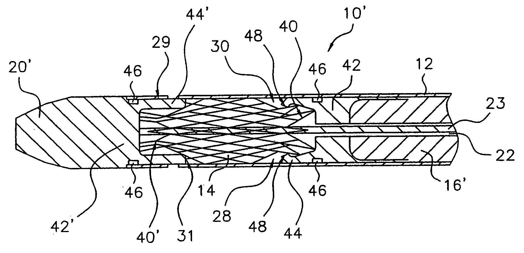
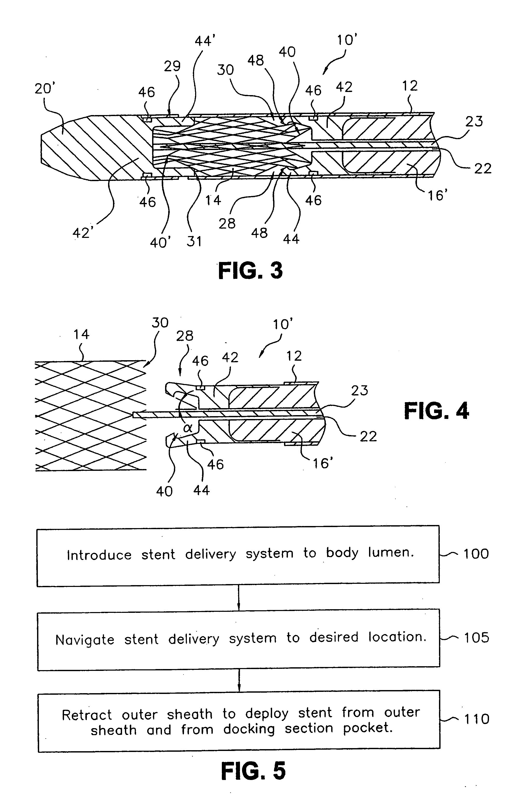
[0025] Referring now to the drawing, wherein like reference numerals refer to like elements throughout, FIGS. 3-4 illustrate an exemplary stent delivery system 10′ of the present invention, having an exemplary docking pusher 16′ and docking catheter tip 20′. As shown in FIG. 3, stent delivery system 10′ comprises an outer sheath 12, central lumen 22, and central core 23, similar to delivery systems known in the art. As used herein, the term “system” shall encompass both a completed assembly which is capable of deploying a stent or a sub-assembly which is capable of deploying a stent when combined with other components. Docking pusher 16′ and catheter tip 20′, however, comprise docking sections 42 and 42′ respectively, each docking section having a pocket 40 and 40′, respectively. Docking section 42 located at pusher distal end 28 is adapted to hold proximal end 30 of compressed stent 14, whereas docking section 42 located at catheter tip proximal end 29 is adapted to hold distal end...


PUM


Abstract

A delivery system for delivering an endoluminal implant to a distal deployment location inside a body lumen from a proximal access location outside the lumen. The system comprises the implant, a catheter, and a slidable sheath having an advanced position in which the sheath covers the implant and a retracted position in which the implant is exposed. The catheter comprises a stabilizer having a distal end adjacent the implant proximal end and / or a catheter tip attached to a central core slideably disposed relative to the implant and having a proximal end adjacent the implant distal end. The catheter tip proximal end and / or the stabilizer distal end comprises a docking section adapted to releasably engage a portion of the implant. Each docking section has an engagement geometry comprising a flared engagement surface that extends inside a short axial length of the implant or a pocket having a bottleneck geometry.

Description

CROSS-REFERENCE TO RELATED APPLICATIONS [0001] This application is a continuation of U.S. patent application Ser. No. 09 / 573,273, filed May 18, 2000, which claims priority from U.S. Provisional Patent Application Serial No. 60 / 134,971, filed on May 20, 1999, both of which are herein incorporated by reference.TECHNICAL FIELD [0002] The present invention relates generally to endoluminal grafts or “stents” and, more specifically, to stent delivery systems or “introducers”. BACKGROUND OF THE INVENTION [0003] A stent is an elongated device used to support an intraluminal wall. In the case of a stenosis, a stent provides an unobstructed conduit for blood in the area of the stenosis. Such a stent may also have a prosthetic graft layer of fabric or covering lining the inside or outside thereof, such a covered stent being commonly referred to in the art as an intraluminal prosthesis, an endoluminal or endovascular graft (EVG), or a stent-graft. As used herein, however, the term “stent” is a ...

Claims


Application Information

Patent Timeline
Patent Type & Authority Applications(United States)
IPC IPC(8): A61F2/06A61F2/82A61F2/84
CPCA61F2/95A61F2002/9665A61F2002/9505
Inventor HIJLKEMA, LUKAS J.FRIEL, FIONNANMCMAHON, MICHAEL
Owner LIFEPORT SCI
Why Eureka
Try Eureka