Audio network distribution system

a distribution system and audio network technology, applied in the direction of data switching network, selective content distribution, instruments, etc., can solve the problems of difficult expansion of audio sources that can be heard through speakers embedded in walls or other places, system flexibility is not very good, and the effect of hard expansion of audio sources

a distribution system and audio network technology, applied in the direction of data switching network, selective content distribution, instruments, etc., can solve the problems of difficult expansion of audio sources that can be heard through speakers embedded in walls or other places, system flexibility is not very good, and the effect of hard expansion of audio sources

US20050131558A1Active Publication Date: 2005-06-16CLEARONCE COMM INC

Image

  • Audio network distribution system
  • Audio network distribution system
  • Audio network distribution system

Examples


Embodiment Construction

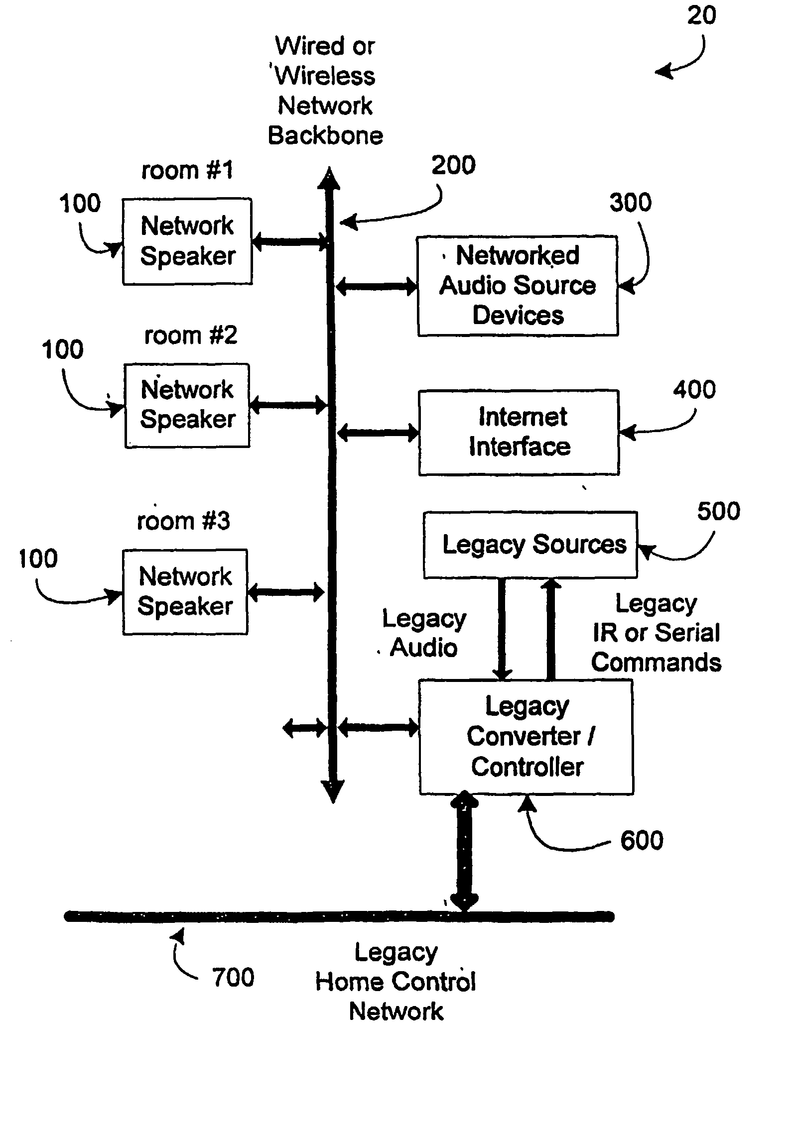
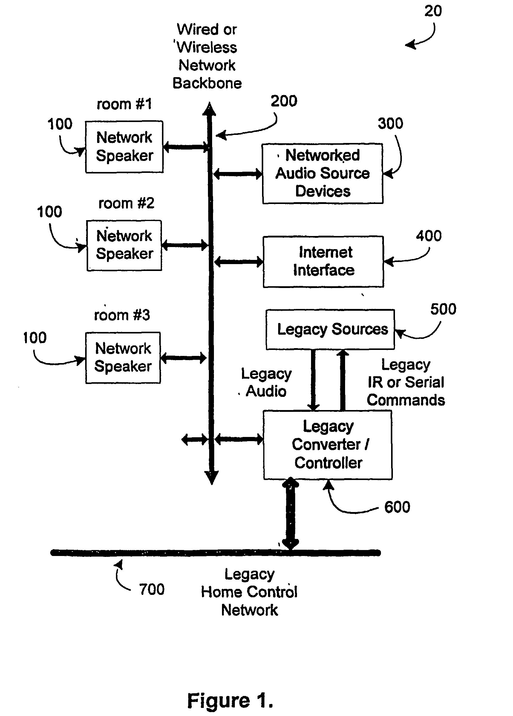
[0016] An audio distribution network system 20 (FIG. 1) includes a plurality of speaker node units 100 which are coupled to a Transport Control Protocol / Internet Protocol (TCP / IP) based network backbone 200. Also coupled to the network backbone 200 are networked audio source node devices 300, an Internet service interface 400, and a Legacy converter / controller 600. Legacy sources 500 provide analog or digital linear PCM_(Pulse Coded Modulation)_audio to be converted into a packet switched digital_coding for transport across the network. They will also provide analog video which will be used for control status feedback, as well as conversion to a packet switched_digital coding for transport across the network. In addition, the Legacy sources 500_will also receive IR or serial commands from the converter / controller 600 which also communicates with a Legacy home control network 700. Some legacy sources_500 may also provide serial communications to the converter / controller 600.

[0017] T...


PUM


Abstract

An audio distribution network system (20) allowing an audio distribution system to be created that is integrated with the home automation system into a home network that permits vocal feedback, status and even control with the audio through network speakers (100).

Description

BACKGROUND OF THE INVENTION [0001] Currently, most audio speakers are passive devices that receive an analog or digital audio signal. A few advanced models have limited self-diagnostics that can be communicated out over additional wire runs as well. These speakers are usually wired to racks or source switching pre-amps and amplifiers. The problem with this approach is that these systems are not very flexible. It is hard to expand the audio sources that can be heard through the speakers embedded in walls or other places after the system has been installed without buying and installing additional costly components. Other audio sources include as home control system voice communication, intercom audio, soundtracks for CD-ROM games, solid-state sound memories. Digital audio broadcasting systems, and even Internet audio can not easily be added and routed through to the existing speakers at a future date if the existing system was not originally designed to input and handle it. This is mo...

Claims


Application Information

Patent Timeline
16 Jun 2005
Publication
US20050131558A1
IPC
G06F17/00; H04L12/28; H04L12/56; H04N7/24; H04R5/02; H04R27/00
CPC
H04N21/234327; H04N21/2662; H04R5/02; H04W4/18; H04R2227/003; H04R2420/07; H04R27/00; G06F3/16
Inventors
BRAITHWAITE, MICHAEL; CARDENAS, HERMAN