Piezoelectric microvalve

a piezoelectric micro-valve and actuator technology, applied in the direction of valve details, valve arrangement, circuit elements, etc., can solve the problems of difficult piezoelectric micro-valves that can accurately control fluid flow at low pressure and high flow rate, piezoelectric micro-valves suited for harsh environments

Inactive Publication Date: 2005-06-23
GENERAL ELECTRIC CO
View PDF24 Cites 21 Cited by
  • Summary
  • Abstract
  • Description
  • Claims
  • Application Information

AI Technical Summary

Problems solved by technology

For example, such actuators have been used in microvalves, but it has been difficult to provide a piezoelectrically operated microvalve that can accurately control fluid flows at low pressures and high flow rates.
In addition, known piezoelectric microvalves are typically complex, difficult to manufacture, and are, therefore, relatively expensive structures that may be susceptible to “stiction” of the moving parts and may not be suited for harsh environments, such as in high temperature applications.

Method used


Image

  • Piezoelectric microvalve
  • Piezoelectric microvalve
  • Piezoelectric microvalve

Examples


Embodiment Construction

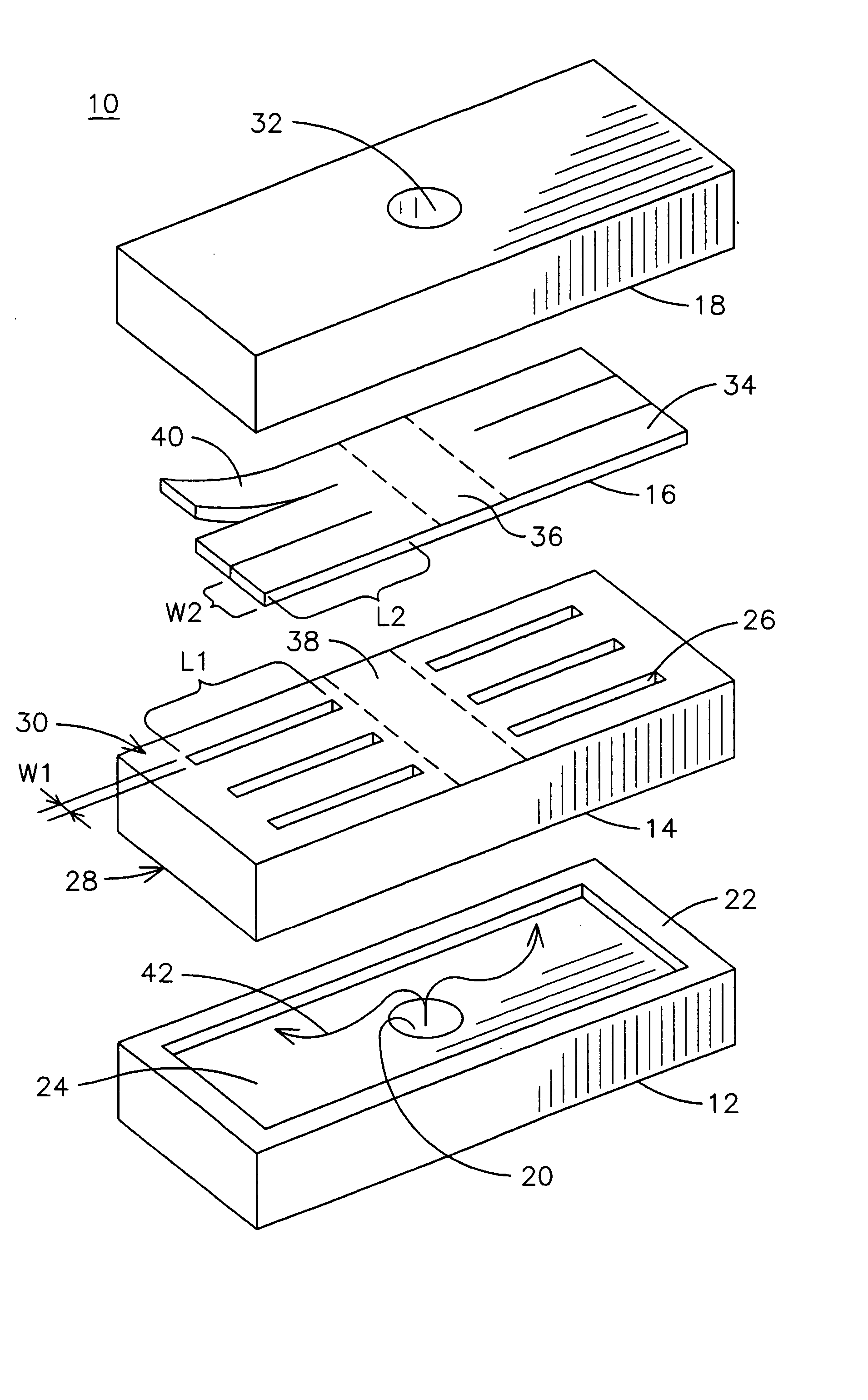
[0007]FIG. 1 is an exploded perspective view of an exemplary piezoelectric microvalve 10. In general, the microvalve 10 includes an inlet plenum 12, a flow directing structure 14, a piezoelectric bending actuator 16 and an outlet plenum 18. The inlet plenum may include a gas inlet opening 20 for receiving a fluid flow 42, such as a cooking gas, into the plenum 12. The inlet opening 20 may be configured to allow connection to a gas pipe, such as typically used in a gas cooking appliance. The inlet plenum 12 may also include a recessed area 24 for distributing gas in the plenum 12, and a lip 22 for sealing against an inlet side 28 of the flow directing structure 14. In an aspect of the invention, the lip 22 may include a gasket mounted between the inlet plenum 12 and the flow directing structure 14. The outlet plenum 18 may be similarly constructed and adapted for placing against an outlet side 30 of the flow directing structure 14. In a further aspect of the invention, the inlet plen...


PUM


Abstract

A piezoelectric microvalve and method for controlling a fluid flow through a piezoelectric microvalve are provided. The microvalve includes an inlet plenum and a flow directing structure for directing a fluid flow, wherein a first side of the structure is in fluid communication with the inlet plenum. The microvalve also includes a piezoelectric bending actuator comprising a flap portion responsive to a command signal for controlling a fluid flow through the flow directing structure. The microvalve further includes an outlet plenum in fluid communication with a second side of the flow directing structure.

Description

FIELD OF THE INVENTION [0001] The present invention is generally related to piezoelectric actuators, and, more particularly, to a piezoelectric microvalve. BACKGROUND OF THE INVENTION [0002] Piezoelectric materials are known to change dimensions upon application of electric field. This phenomenon allows the use of piezoelectric material to be used as actuators in micro-electro-mechanical system (MEMS) devices. For example, such actuators have been used in microvalves, but it has been difficult to provide a piezoelectrically operated microvalve that can accurately control fluid flows at low pressures and high flow rates. In addition, known piezoelectric microvalves are typically complex, difficult to manufacture, and are, therefore, relatively expensive structures that may be susceptible to “stiction” of the moving parts and may not be suited for harsh environments, such as in high temperature applications. BRIEF DESCRIPTION OF THE INVENTION [0003] A microvalve is described herein as...

Claims


Application Information

Patent Timeline
Patent Type & Authority Applications(United States)
IPC IPC(8): F15C5/00F16K31/00F16K31/02F16K99/00
CPCF15C5/00F16K31/005F16K2099/008F16K99/0007F16K99/0048F16K99/0001
Inventor SEELEY, CHARLES ERKLINSAIA, RICHARD JOSEPHKAPUSTA, CHRISTOPHER JAMESNAJEWICZ, DAVID JOSEPHZRIBI, ANIS
Owner GENERAL ELECTRIC CO
Why Eureka
Try Eureka