Transflective liquid crystal display panel and apparatus and method of driving the same

Active Publication Date: 2005-06-23
LG DISPLAY CO LTD
View PDF7 Cites 7 Cited by
  • Summary
  • Abstract
  • Description
  • Claims
  • Application Information

AI Technical Summary

Benefits of technology

[0034] An object of the present invention is to provide a transflective liquid crystal display panel with an improved response time.
[0035] Another object of the present invention is to provide a transflective liquid crystal display panel with a wide viewing angle.
[0036] Another object of the present invention is to provide an apparatus for driving a transflective liquid crystal display panel having an improved response time.
[0037] Another object of the

Problems solved by technology

Thus, it is difficult to optimize the brightness of the reflective portion RP and the transmissive portion TP.
However, since the liquid crystal display panel of the ECB mode has a response speed of several tens of milliseconds and a narrow viewing angle, it is difficult to use the ECB mode liquid crystal display panel when a wide viewing angle is required.
Accordingly, when displaying moving pictures, which require higher response time than sti

Method used


Image

  • Transflective liquid crystal display panel and apparatus and method of driving the same
  • Transflective liquid crystal display panel and apparatus and method of driving the same
  • Transflective liquid crystal display panel and apparatus and method of driving the same

Examples


first embodiment

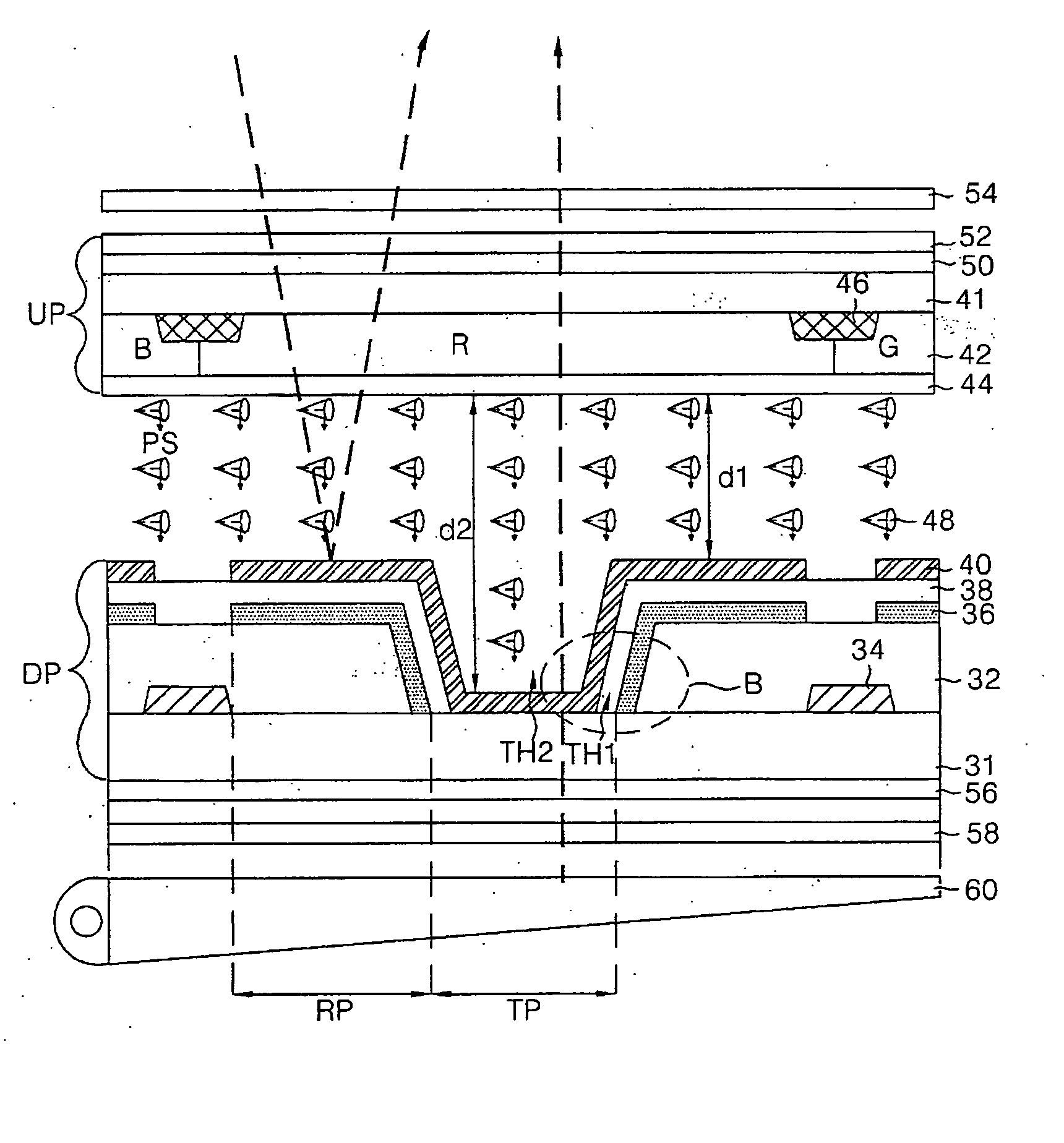
[0060]FIG. 6 is a sectional view of an exemplary transflective liquid crystal display panel having a ferroelectric liquid crystal material injected therein according to the present invention. The transflective liquid crystal display device shown in FIG. 6 includes an upper plate UP and a lower plate DP. A ferroelectric liquid crystal material 48 is positioned between the upper plate UP and the lower plate DP. A liquid crystal display with such a configuration is suitable for a moving picture display because the injection of the ferroelectric material 48 between the upper plate and the lower plate leads to a higher speed response characteristic in comparison with a TN mode liquid crystal cell or another type of liquid crystal cell.

[0061] The ferroelectric liquid crystal (FLC) material 48 has a layered structure with similar electric and magnetic properties. The FLC rotates along a virtual cone in response to an applied electric field. When the external electric field is not applied t...

second embodiment

[0070]FIG. 7 is a sectional view illustrating an exemplary transflective liquid crystal display panel having a ferroelectric liquid crystal material operating in a half V-switching mode injected therein according to the present invention. The transflective liquid crystal display device depicted in FIG. 7 includes an upper plate UP and a lower plate DP. A ferroelectric liquid crystal material 118 operating in a half V-switching mode is positioned therebetween. A reflective plate 106 is formed in the lower plate DP. Upper and lower retardation films 122 and 126 and upper and lower polarizers 124 and 128 are deposited on the exteriors of the upper plate UP and the lower plate DP, respectively. A backlight unit 130 is disposed on a rear surface of the lower polarizer 128.

[0071] The backlight unit 130 generates light required for displaying pictures in a transmissive mode of a liquid crystal panel. Each of the upper and the lower retardation films 122 and 126 is formed at the exterior of...


PUM


Abstract

A transflective liquid crystal display panel includes a ferroelectric liquid crystal cell operating in a half V-switching mode. The ferroelectric liquid crystal cell includes a reflective portion and a transmissive portion. A cell gap of the reflective portion is similar to a cell gap of the transmissive portion. A voltage applied to the ferroelectric liquid crystal cell depends on a brightness level of ambient light.

Description

[0001] This application claims the benefit of Korean Patent Application No. 2002-092692 filed in Korea on Dec. 17, 2003, which is hereby incorporated by reference. BACKGROUND OF THE INVENTION [0002] 1. Field of the Invention [0003] The present invention relates to a liquid crystal display panel, and more particularly, to a transflective liquid crystal display panel and an apparatus and a method of driving the same capable of improving response time as well as providing a wide viewing angle. [0004] 2. Description of the Related Art [0005] Generally, an active matrix liquid crystal display (LCD) device displays a natural moving picture by using a thin film transistor (hereinafter referred to as a TFT) as a switching device. Such an active matrix LCD device can be made smaller than a cathode ray tube CRT. Thus, active matrix LCD devices have been used as monitors for portable televisions and lap-top computers. [0006] A liquid crystal display device is not self-luminous and thus, requir...

Claims


Application Information

Patent Timeline
IPC IPC(8): G02F1/133G02F1/1335G02F1/141G09G3/36
CPCG02F1/133555G09G3/3648G02F2203/30G02F1/1416G02F1/133
Inventor CHOI, SU SEOK
Owner LG DISPLAY CO LTD
Why Eureka
Try Eureka