Base isolation device for structure

a technology for isolation devices and structures, applied in bridges, girders, ways, etc., can solve the problems of narrow ranges capable of obtaining effective base isolation functions, difficult setting, and difficult to attach weights that were 10% the weight of the entire structure, and achieve the effect of suppressing vibration in the out-of-plane direction

Inactive Publication Date: 2005-06-30
NIHON UNIVERSITY
View PDF7 Cites 20 Cited by
  • Summary
  • Abstract
  • Description
  • Claims
  • Application Information

AI Technical Summary

Benefits of technology

[0012] Taking these prior problems into consideration, the object of this invention is to provide a base isolation device for a structure that is capable of effectively suppressing vibration in the out-of-plane direction of the structural members of a structure.

Problems solved by technology

In this kind of prior art, there still remain the following problems that must be improved.
In other words, in the prior art described above, in order to efficiently suppress the vertical vibration in the floor slab 3, it is necessary to properly set the elastic coefficient of the elastic member 4 and the damping coefficient of the damping member 5 in accordance to the characteristic natural frequency of the floor slab 3, however, in order to do this, there is a problem in that the range capable of obtaining an effective base isolation function is narrow, and the setting of which is difficult.
Moreover, the weight member 6 is more effective the heavier it is, however, in an actual structure, it was difficult to attach a weight that was 10% the weight of the entire structure.
Furthermore, since the weight member 6 acts only in the direction of gravitational acceleration, installing this prior base isolation device in the structural members of an inclined roof, or the structural-support members of a vertically placed glass curtain wall was impossible.

Method used


Image

  • Base isolation device for structure
  • Base isolation device for structure
  • Base isolation device for structure

Examples


Embodiment Construction

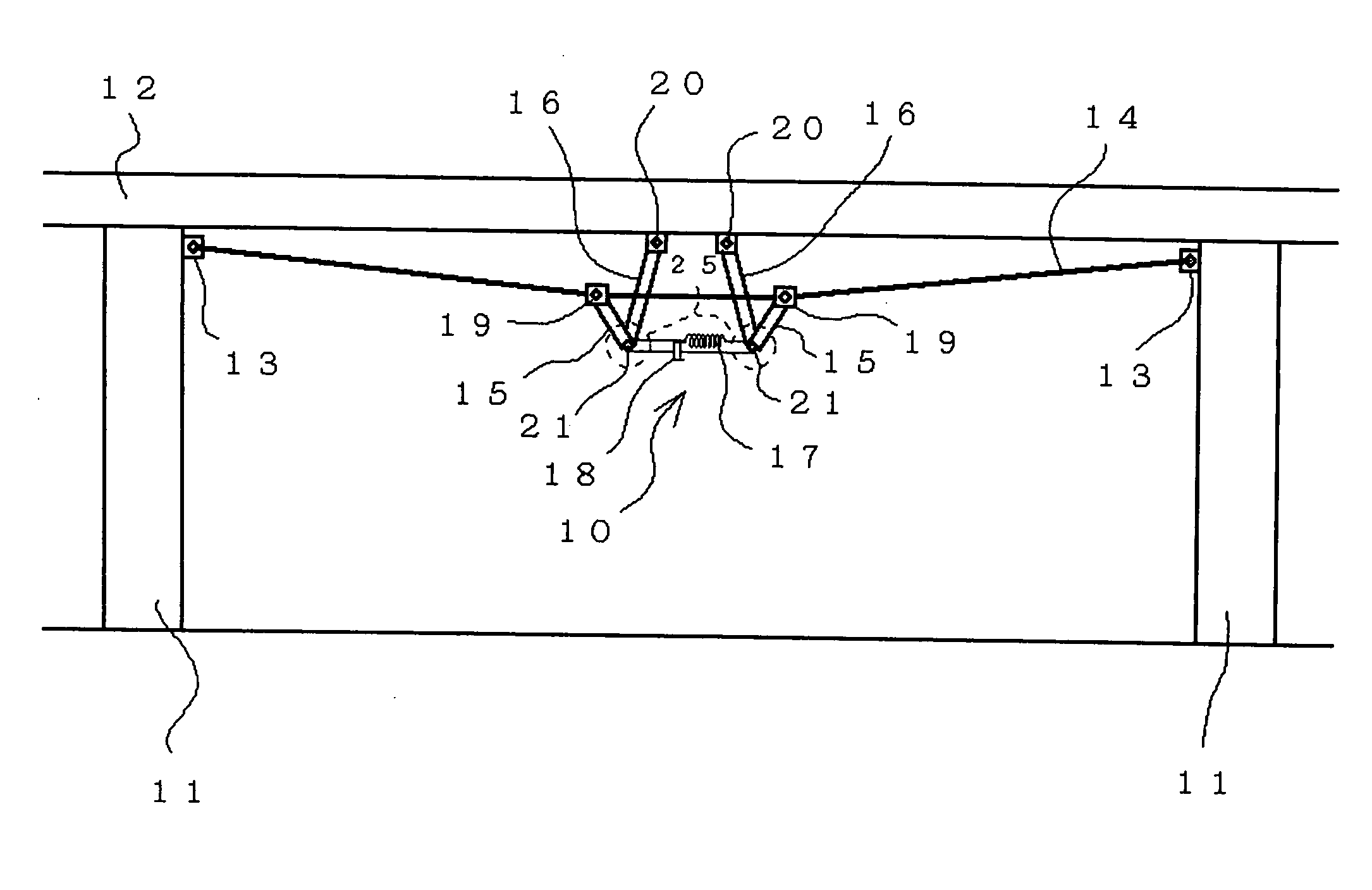
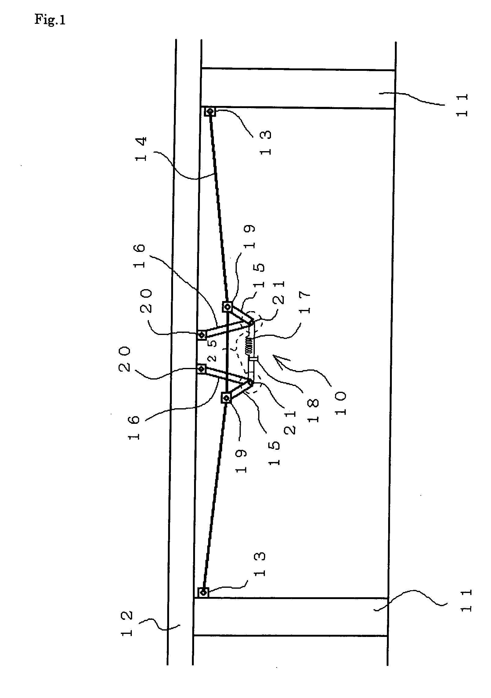
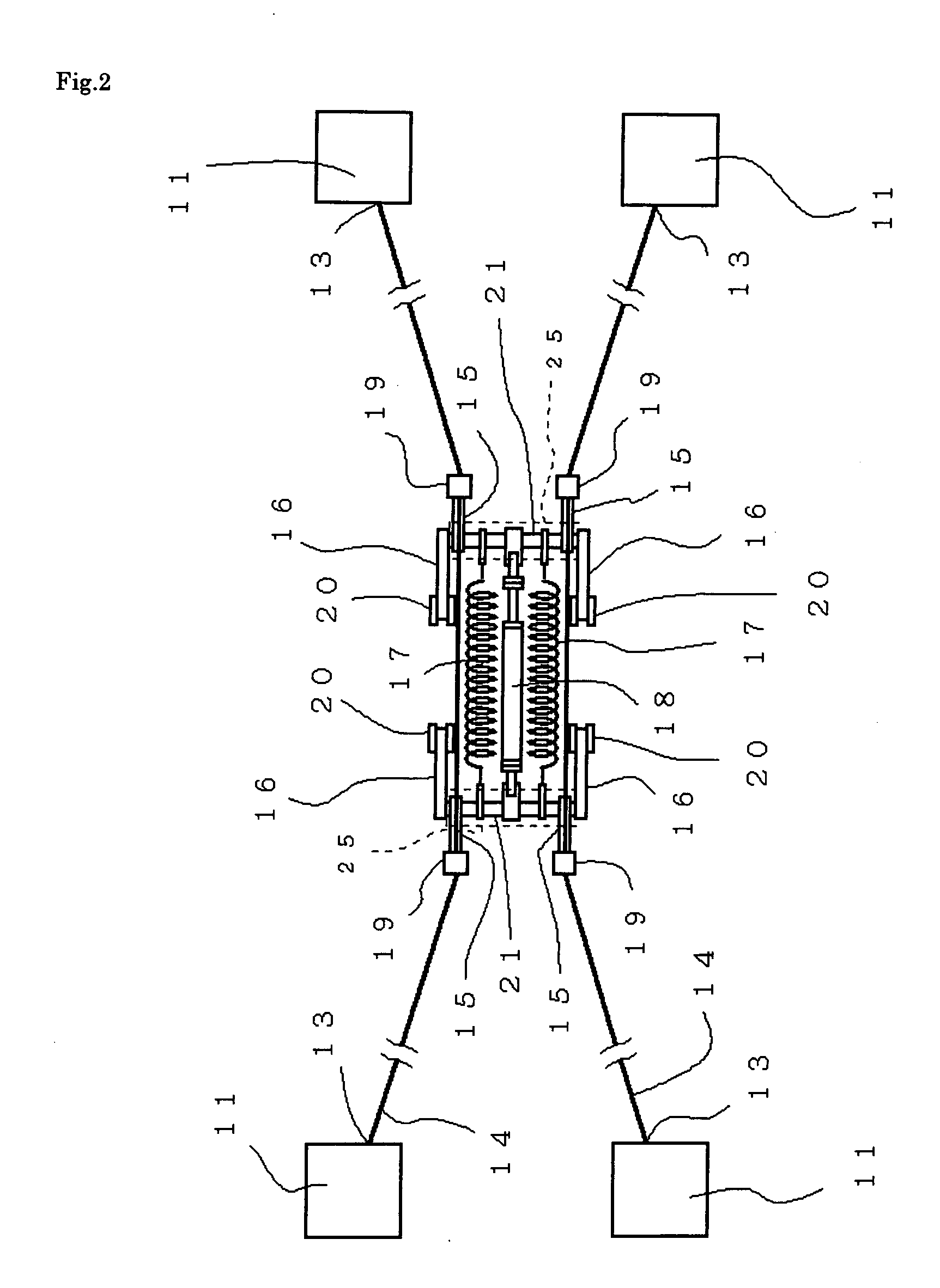
[0034] A first embodiment of the present invention will be explained below with reference to FIG. 1 to FIG. 3.

[0035] The base isolation device 10 for a structure of this embodiment, which is indicated by the reference number 10 in FIG. 1, is applied to a floor slab 12, which is a structural member that is supported by a plurality of bridge supports 11, and is basically constructed by comprising: support points 13 that are located underneath the floor slab 12 and separated by a specified space (in this embodiment, they are located on adjacent bridge supports 11), and where a tension member 14 is placed in between these support points 13 having an overall length that is longer than the space, and where first link pieces 15 are connected to points along the tension member 14 such that they can rotate freely, and second link pieces 16 that are connected between the first link pieces 15 and the floor slab 12 such that they can rotate freely; an energizing member 17 that applies tension ...


PUM


Abstract

A base isolation device for a structure capable of efficiently and effectively suppressing the vibration of a structural body in surface outside direction, wherein a tension member having on overall length longer than an interval between support points provided on the structural body at a specified interval is disposed between the support points, one end parts of first link pieces are rotatably connected midway to the tension member directly or through rigid members, one end parts of second link pieces are rotatably connected to the structural body, the other end parts of the first link pieces are rotatably connected to the other end parts of the second link pieces, and an energizing member providing a tension to the tension member by energizing the first link piece and the second link piece and a damping member operated by the rotation of the first link piece and the second link piece are installed between the structural body forming the structure and connection parts between the first link pieces and the second link pieces.

Description

BACKGROUND OF THE INVENTION [0001] 1. Field of the Invention [0002] This invention relates to a base isolation device for a structure, and more particularly to a base isolation device for a structure that is applied to a structure having structural members such as slabs in elevated freeways, elevated railway tracks, or bridge constructions, and suppresses vibration in the out-of-plane direction of the structural members. [0003] Moreover, the invention can also be applied to a base isolation device that suppresses vibration in the out-of-plane direction of structural members of an inclined roof, or structural-support members of a vertically placed glass curtain wall. [0004] 2. Description of the Related Art [0005] In recent years, various measures have been employed for suppressing damage such as collapse or failure of structures comprising structural elements such as the slabs in elevated freeways, elevated railway tracks, or bridge constructions due to vertical vibration of the str...

Claims


Application Information

Patent Timeline
Patent Type & Authority Applications(United States)
IPC IPC(8): E01B26/00E01D19/00E04C3/18E04H9/02
CPCE01B26/00E01D19/00E04H9/028E04H9/02E04C3/18E04H9/0235E04H9/0237E01D19/04
Inventor ISHIMURA, SHINJIISHIGAKI, HIDENORI
Owner NIHON UNIVERSITY
Why Eureka
Try Eureka