Insulated fireplace

Inactive Publication Date: 2005-06-30
DENG DAVID
View PDF10 Cites 13 Cited by
  • Summary
  • Abstract
  • Description
  • Claims
  • Application Information

AI Technical Summary

Benefits of technology

[0003] The present invention is an insulated glass design for a fireplace. The insulated glass design comprises of two layers of glasses separated by a thin layer of air space with free flowing air through the air space to cool the glasses. In the preferred embodiment, a fan is placed under the two layers of glasses to force cooler

Problems solved by technology

However, the high temperature glass itself is heated to such a high temperature that mere contact with the glass will result in burns to the skin.
This poses dangers to people ar

Method used


Image

  • Insulated fireplace
  • Insulated fireplace
  • Insulated fireplace

Examples


Example

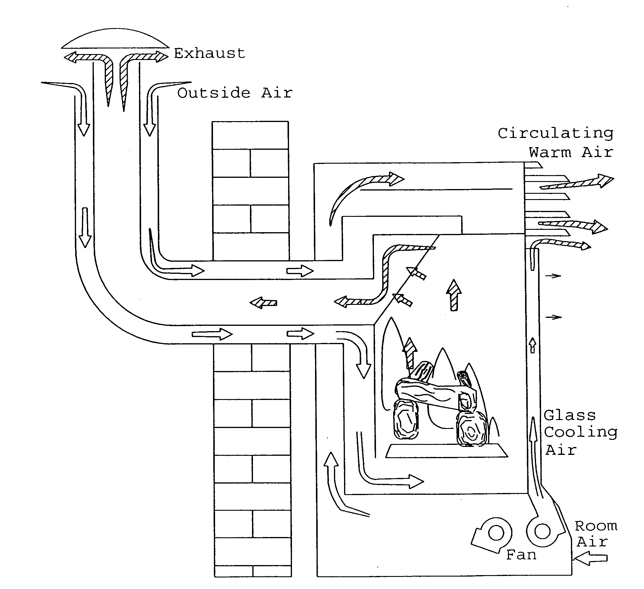
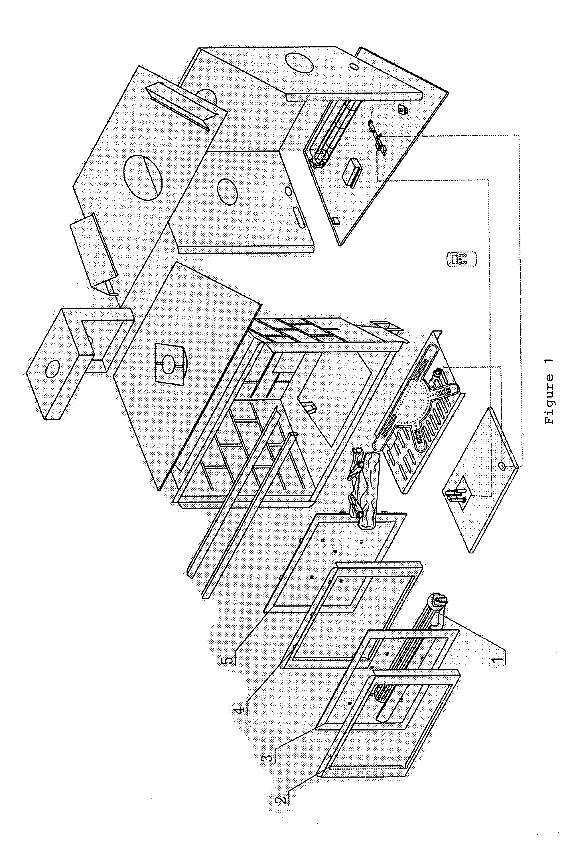
[0006]FIG. 1 shows an exploded view of the preferred embodiment of the insulated fireplace. A first layer of glass 5 in affixed to the front of a conventional fireplace with a frame 4. A second layer of glass 3 is affixed in front of the first layer of glass 5 with a second frame 2. The first layer of glass 5 and the second layer of glass 3 is separated by a thin layer of air space that allows air to enter between the layers of glasses from the bottom and exit through the top to carry away the heat from the two layers of glasses 3, 5. The two sides of the air space are sealed by the second frame 2. The two layers of glasses 3, 5 are affixed to the front of a conventional fireplace. A fan 1 is affixed under the two layers of glasses 3, 5 to force air through the thin layer of air space to cool the two layers of glasses 3, 5 more quickly and effectively.

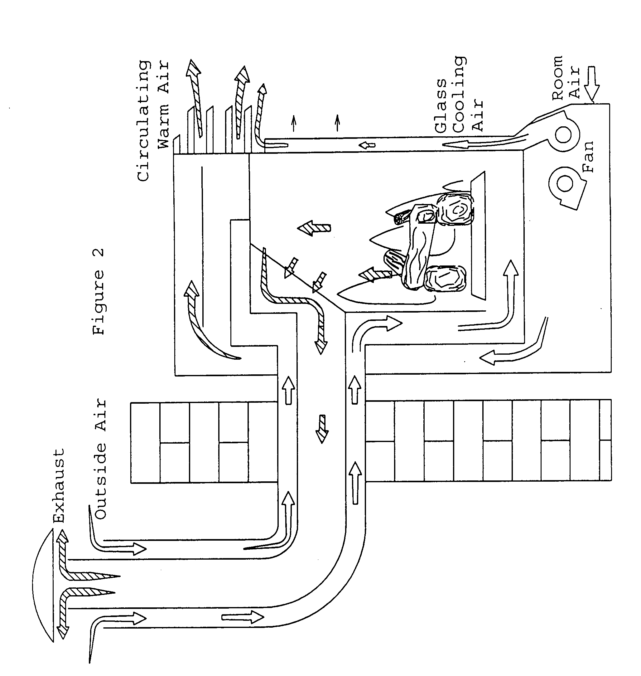
[0007] As shown in FIG. 2, the fan 1 will pull air from inside the room to force cooler air from inside the room through the air spa...


PUM


Abstract

An insulated glass design for a fireplace comprising two layers of glasses separated by a thin layer of air space with free flowing air through the air space to cool the glasses. In the preferred embodiment, a fan is placed under the two layers of glasses to force cooler air through the air space to remove the heat from the two layers of glasses quickly and more effectively. The insulated glass design will effectively and greatly reduce the surface temperature of the glass such that skin burns due to contact with the glass is minimized or eliminated.

Description

BACKGROUND FIELD OF INVENTION [0001] The present invention relates generally to an enclosed fireplace. More specifically, the present invention relates to an insulated glass design for a fireplace. BACKGROUND-DESCRIPTION OF RELATED ART [0002] Fireplaces are often used to heat a home. Fireplaces are also an aesthetic addition to the decor in the home. The fireplace may use real wood logs or natural gas with artificial simulated fire logs to generate heat. The fire that is burning in the fireplace is at a very high temperature. Generally, a shield such as clear high temperature glass is used to shield the flame from the inside of the home and to prevent accidental contact with the flame. However, the high temperature glass itself is heated to such a high temperature that mere contact with the glass will result in burns to the skin. This poses dangers to people around the fireplace, particularly when curious children are playing around the fireplace. Furthermore, the high temperature g...

Claims


Application Information

Patent Timeline
IPC IPC(8): F24B1/18F24B13/00F24C3/00F24C5/00F24C15/00
CPCF24B1/1808F24C15/002F24B13/004F24C3/004F24C15/006
Inventor DENG, DAVID
Owner DENG DAVID
Why Eureka
Try Eureka