Roll bar structure of vehicle

a technology of rolling bar and vehicle, which is applied in the direction of vehicle components, superstructure sub-units, belt anchoring devices, etc., can solve the problems of insufficient resistance of the roll bar welded connection to be released, and difficulty in connecting firmly, so as to increase the resistance properly against the vehicle rollover

Inactive Publication Date: 2005-06-30
MAZDA MOTOR CORP
View PDF17 Cites 47 Cited by
  • Summary
  • Abstract
  • Description
  • Claims
  • Application Information

AI Technical Summary

Benefits of technology

[0004] The present invention has been devised in view of the above-described problems, and an object of the present invention is to provide a roll bar structure of a vehicle which can increase properly its resistance against the vehicle rollover by connecting firmly the roll bar with the crossbar.

Problems solved by technology

In the conventional roll bar structure of a vehicle, however, since the member extending in the vehicle width direction and the roll bar extending upward are abutted and welded there, there is concern that a large load applied to the roll bar during the vehicle rollover and the like may cause the welded connection to be released and thus a resistance of the roll bar against the vehicle rollover may not increase sufficiently.
Herein, it is generally difficult to connect firmly such a bent-shaped roll bar with a crossbar extending in the vehicle width direction.

Method used


Image

  • Roll bar structure of vehicle
  • Roll bar structure of vehicle
  • Roll bar structure of vehicle

Examples


Embodiment Construction

[0058] Hereinafter, preferred embodiments of the present invention will be described referring to the accompanying drawings. It should be understood that even though embodiments are separately described, single features thereof may be combined to additional embodiments.

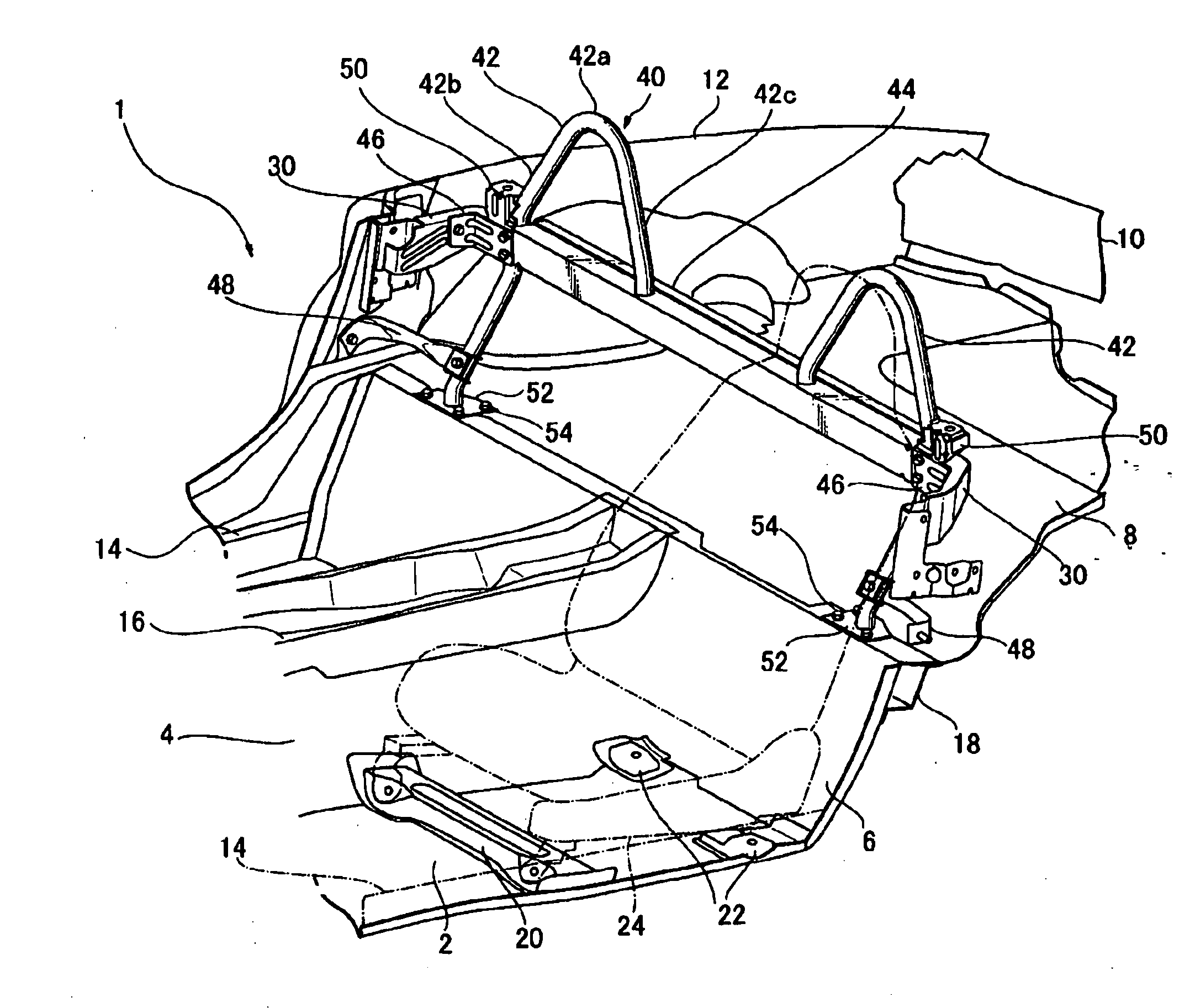
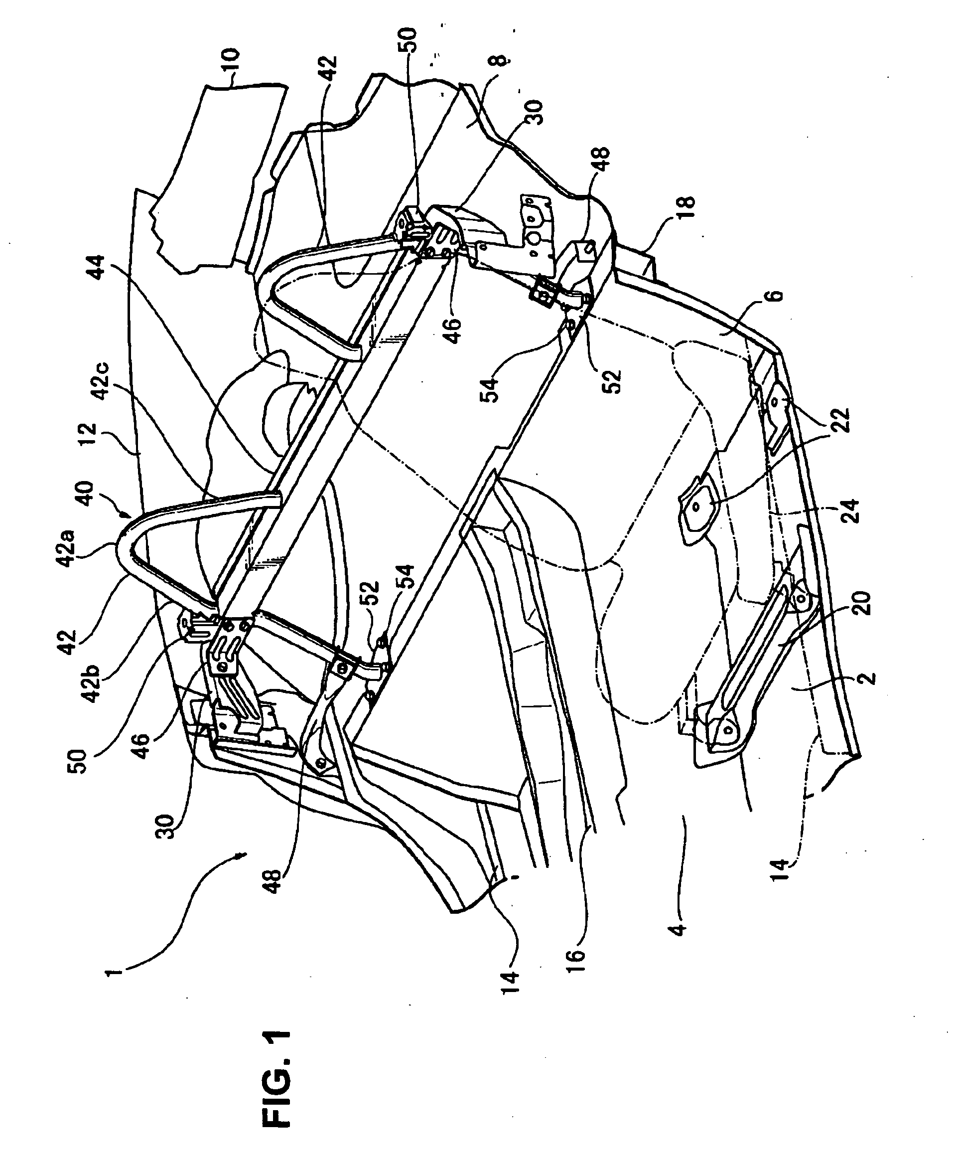
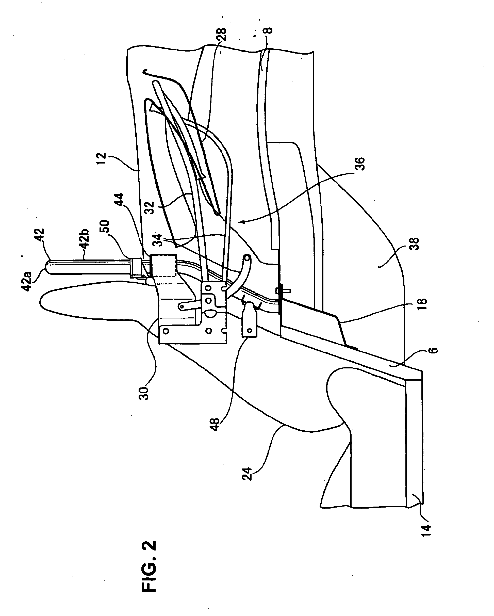
[0059]FIG. 1 is a perspective view illustrating a rear portion of a vehicle equipped with a roll bar structure of the vehicle according to an embodiment of the present invention. FIG. 2 is a side view, when viewed from left, of the rear potion of the vehicle equipped with the roll bar structure of the vehicle according to the embodiment of the present invention.

[0060] A vehicle 1 comprises, as illustrated in FIG. 1, a floor panel 2 which constitutes a cabin floor, a floor tunnel 4 which projects upward from the floor panel 2 and extends longitudinally, a kickup panel 6 which extends slat, i.e., upward and rearward, at a rear end portion of the floor panel 2 and the floor tunnel 4, a rear floor panel 8 which extends ...


PUM


Abstract

The present invention relates to a roll bar structure of a vehicle equipped with side panels and an open top, comprising a crossbar having a closed section and extending in a vehicle width direction between both of the side panels, roll bars having a reverse-U shape and at least part thereof projecting above the crossbar, and through holes formed at upper and lower portions of the crossbar, wherein an one-side part of roll bar extending substantially vertically penetrates the through holes, and the roll bars are connected respectively with the upper and lower portions of the crossbar which the roll bars penetrate. Accordingly, a resistance of the roll bar structure against a vehicle rollover can be increased by connecting firmly the roll bars with the crossbar.

Description

BACKGROUND OF THE INVENTION [0001] The present invention relates to a roll bar structure of a vehicle, and more specifically to a roll bar structure of a vehicle equipped with an open top and a side panel forming a vehicle side face. [0002] In recent years, a so-called open car equipped with an open top has had a roll bar which is provided over a vehicle body to protect a driver's head during a vehicle rollover. It is known that such a roll bar is connected with a reinforcement member extending in a vehicle width direction in order to increase its resistance against the vehicle rollover. For example, Japanese Patent Laid-Open Publication No. 11-115662 discloses a roll bar structure of a vehicle, in which both ends of a base portion extending in the vehicle width direction are fixed respectively to side bodies of an automotive vehicle, and both ends of a pair of reverse-U-shaped members extending upward are fixed to this base portion by welding. Also, Japanese Patent Laid-Open Public...

Claims


Application Information

Patent Timeline
Patent Type & Authority Applications(United States)
IPC IPC(8): B60R21/13B60R22/18B62D25/08
CPCB60R21/13B62D25/087B60R2021/132B60R22/18
Inventor MIKI, KENJIROKIMURA, TAKAYUKIEBISUGI, TAKASHIFUJII, YUKARIMASUDA, MASATAKA
Owner MAZDA MOTOR CORP
Why Eureka
Try Eureka