

Magnetic recording medium
- Summary
- Abstract
- Description
- Claims
- Application Information
AI Technical Summary
Benefits of technology
Problems solved by technology
Method used
Image

Examples
embodiment 1
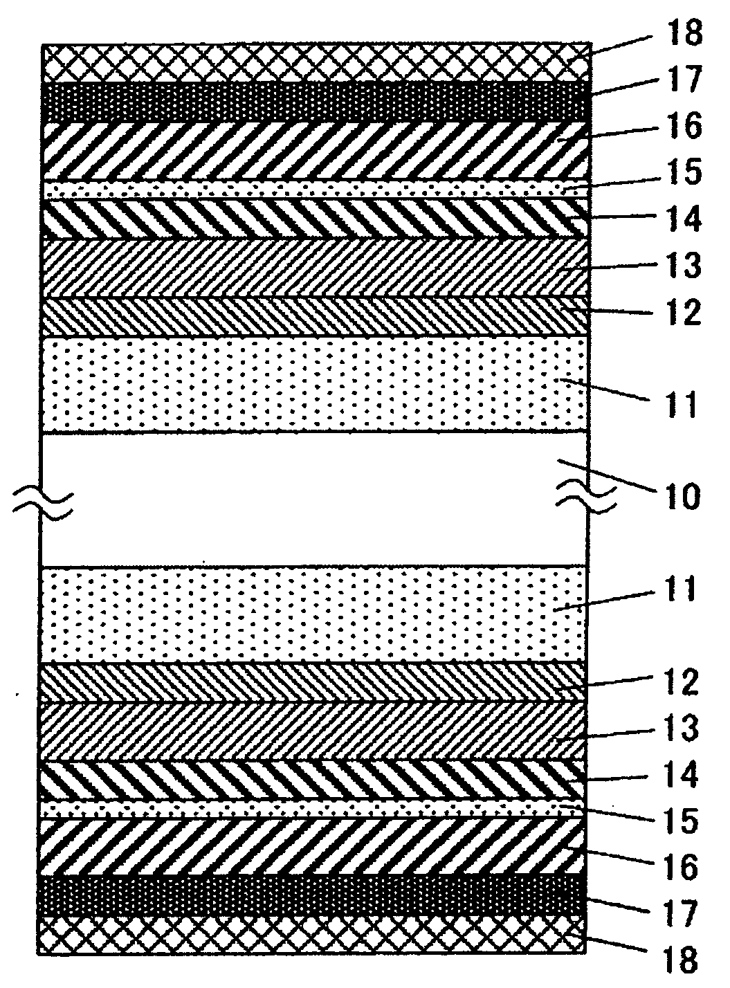
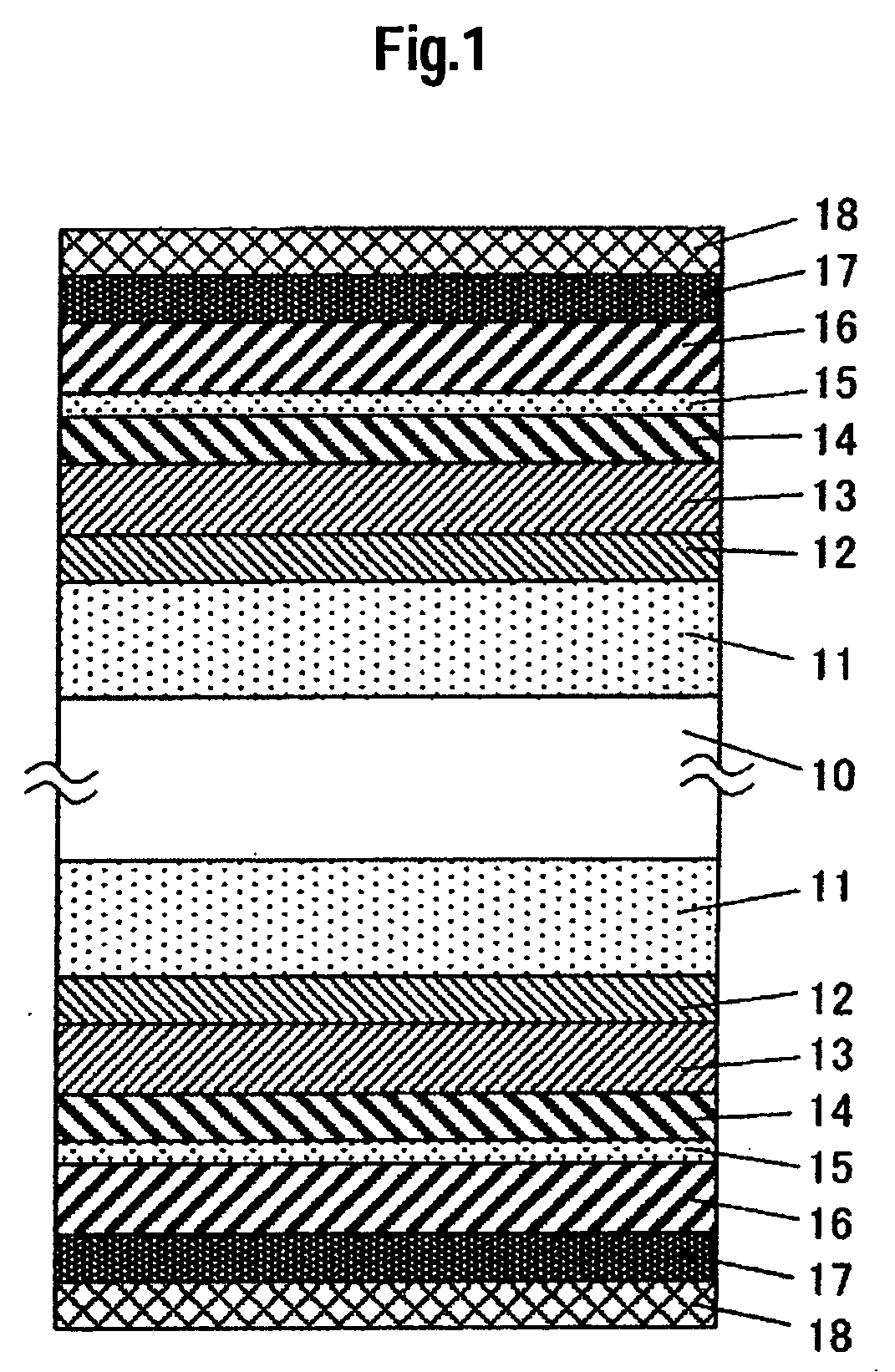
[0037]FIG. 1 shows a cross-sectional structural view of one embodiment of a magnetic recording medium according to the present invention. An alumino silicate glass substrate 10 with a chemically strengthened surface was put to alkali cleaning and dried and then an Ni-40 at. % Ta alloy layer of 30 nm thick as a first underlayer 11, and a W alloy layer of 1 nm thick as a second underlayer 12 were formed at room temperature. After heating the substrate to a temperature of about 240° C. by a lamp heater, a Cr-10 at. % Ti-5 at. % B alloy layer of about 10 nm thick was formed as a third underlayer 13. Further, a lower magnetic layer 14 comprising a Co-14 at. % Cr-6 at. % Pt alloy layer of about 3 nm thick, an Ru intermediate layer 15 of about 0.6 nm thick, and an upper magnetic layer 16 comprising a Co-18 at. % Cr-14 at. % Pt-8 at. % B alloy layer of about 18 nm thick were formed successively, and a carbon film 17 of about 3.2 nm thick was formed as a protection layer. For the second unde...
embodiment 2
[0046] After an Ni-40 at. % alloy layer as a first underlayer 11 and a W element or W—Co alloy layer as a second underlayer 12 were formed to have a thickness of about 1 to 16 nm on a glass substrate 10, the substrate was heated to a temperature of about 240° C. by a lamp heater, and a third underlayer 13, magnetic layers (14-16), and a carbon protection film 17 were successively formed in this order. W, W-10 at. % Co, W-30 at. % Co, W-50 at. % Co, W-70 at.% Co and W-90 at. % Co alloys were used for the second underlayer 12 and they were deposited such that the total thickness of the first underlayer 11 and the second underlayer 12 were about 20 nm, 30 nm, and 40 nm. The third underlayer 13 and the magnetic layers (14-16) had layer structures identical with those in Embodiment 1 and the process conditions such as gas atmosphere and tact time were identical with the conditions in Embodiment 1.
[0047] Table 3 shows the magnetic characteristics and the read / write characteristics of the...
embodiment 3
[0059] On a glass substrate applied with concentric texturing to the surface of the substrate, were formed an Ni—Ti alloy, Co—Ti alloy, Ni—Ti—Ta alloy, Co—Ti—Ta alloy, Cr—Ti—Ta alloy, Co—Cr—Zn alloy, Co—Al—Ti alloy, Cr—Ti—Al alloy or Cr—Ta alloy layer as a first underlayer 11 to have a thickness of about 25 nm. After a W-30 at. % Co alloy layer of about 5 nm thick was formed as a second underlayer 12, the substrate was heated to a temperature of about 280° C. by a lamp heater, and a third underlayer 13, magnetic layers 14 to 16 and a protection layer 17 were formed successively. All of the composition, the film thickness, and the deposition process for each of the layers after the heating of the substrate were identical with those for the media in Embodiment 1.
[0060] Table 5 shows the magnetic characteristics and the read / write characteristics of the media in this embodiment.
TABLE 5Speci-Reso-menBr · tHclutionS / NNo.First underlayer[T · nm][kA / m]HcOR[%][dB]301Ni-50 at. % Ti4.77315...
PUM
 Abstract
Description
Claims
Application Information