Magnetic recording and reading device

a reading device and magnetic recording technology, applied in the field of magnetic recording and reading devices, can solve the problems of inability to accurately record on the recording device, inability to perform recording and reading, and increase noise, etc., to achieve the effect of reducing the absolute value of the normalized noise coefficient, reducing noise, and improving noise reduction

Inactive Publication Date: 2007-02-13
WESTERN DIGITAL TECH INC
View PDF73 Cites 9 Cited by
  • Summary
  • Abstract
  • Description
  • Claims
  • Application Information

AI Technical Summary

Benefits of technology

[0020]The reason for the above phenomenon was examined. The present inventors considered that the above phenomenon is due to a bad frequency response in the recording characteristic of the medium. Therefore, the cause was analyzed by performing a simulation through the use of a super computer, etc. and as a result, it became evident that there is a problem in thermal fluctuations of magnetization and spin damping during recording process. Therefore, studies were carried out on medium additives capable of optimizing thermal fluctuations and damping coefficient. As a result, the present inventors found out that by adding at least one element selected from a third group consisting of La, Ce, Pr, Nd, Pm, Sm, Eu, Gd, Tb, Dy, Ho, Er, Tm, Yb, Lu, Bi, Sb, Pb, Sn, Ge and B to the composition of the above medium, it is possible to reduce the absolute value of normalized noise coefficient per recording density to not more than 2.5×10⁻⁸(μVrms) (inch) (μm)0.5 / (μVpp) even when recording is performed at 50 MB / s. This effect was observed when the above elements were added in amounts of not less than 0.1 at %. However, their addition in an amount of 1 at % is sufficient. Addition in amounts of not more than 15 at % was undesirable because of a remarkable decrease in output. Furthermore, the effect was remarkable when rare earth elements were added. The above effect was also ascertained in what is called a granular type medium in which a non-magnetic substance, such as SiO2 and ZrO2, and a magnetic material with a high crystalline anisotropy constant, such as CoPt and CoNiPt, were simultaneously formed by sputtering and the magnetic material with a high crystalline anisotropy constant was precipitated and dispersed by heat treatment at a temperature of about 300° C. to obtain the above composition. Furthermore, in a case where the above magnetic layer is made of an amorphous magnetic substance, the magnetic layer often has perpendicular anisotropy. However, the same effect was also observed in this case. Furthermore, in any of these instances, when the above magnetic layer was formed via a non-magnetic intermediate layer containing at least one element selected from the group consisting of Cr, Mo, W, V, Nb, Ta, Zr, Hf, Ti, Ge, Si, Go, Ni, C and B as a primary component, noise could be remarkably reduced because of statistical addition of signals and this was especially favorable for noise reduction. Furthermore, what is especially noteworthy is that by reducing the magnetic core length of the above magnetic head to not more than 50 μm, a sharp and strong magnetic field could be generated with increased efficiency and recording on a medium with a higher coercive force was possible. This is preferable because higher densities can be obtained. Furthermore, by installing the above R / W-IC near the suspension, the rise time of a recording magnetic field could be made further shorter. This permitted sharp recording and enabled medium noise to be relatively reduced. Therefore, this is more preferable.
[0021]In order to perform recording and reading at a high density of not less than 5 Gb / in2, it was necessary to perform the reading of magnetic information through the use of a magnetic head having an effective read-track width of not more than 0.9 μm with giant magnetoresistive effect or tunneling-magnetoresistive effect, and performs the reading of magnetic information at a high density of not less than 5 Gb / in2. By performing reading like this, a signal-to-noise ratio of not less than 20 dB of the device necessary for the operation of the device was obtained with the aid of the signal processing method and it was necessary to combine the magnetic head with signal processing such as EPRML or EEPRML, trellis coding, ECCs, etc. Incidentally, the giant magnetoresistive element (GMR) and tunneling magnetic head technologies are disclosed in JP-A-61-097906, JP-A-02-61572, JP-A-04-35831, JP-A-07-333015, JP-A-02-148643 and JP-A-02-218904. An effective track width of not more than 0.9 μm was realized by putting lithography technology based on an i-line stepper or a KrF stepper, FIB fabrication technology, etc. to full use.
[0022]The above system was a very epoch-making product as a magnetic disk. However, the present inventors found out that recording can be assisted by instantaneously heating a medium to the temperature range of from about 50° C. to 250° C. with a magnetic disk provided with a heat-generating portion and thereby reducing the coercive force at a high frequency, and that this idea is further effective. In other words, in this system the load put on the recording portion and the material for recording magnetic poles could be reduced, and recording at a high density of not less than 5 Gb / in2 and a high data transfer rate of not less than 50 MB / s was possible even with a recording track width of not more than 0.9 μm and even when a magnetic pole material with a saturation magnetic flux density of 1 T was used. Thus, this was especially advantageous.
[0023]With respect to this effect, access time can also be shortened by performing magnetic recording immediately after heat application to a magnetic recording medium and performing reading with the aid of the above giant magnetoresistive element or element having a tunneling-magnetoresistive effect. This is further preferable.
[0024]Furthermore, by using a semiconductor laser chip as the above heat-generating portion, an effective head volume can be reduced and high-speed positioning becomes possible. This is especially preferable. In addition, in order to shorten access time and ensure positioning with a higher accuracy, it is especially effective to position the head by a rotary actuator method in at least two stages of coarse and fine movement adjustments.

Problems solved by technology

However, the both types greatly rely on heat when recording and reading.
Therefore, according to such type of devices, it is impossible to perform recording and reading in high data transfer rate and thus they have been adopted mainly in backup systems, etc.
However, when the magnetic recording was carried out on that film media of the prior art at a high frequency of not less than 50 MB / s, thermal fluctuation effects in fine magnetic crystallines is remarkable due to weak exchange coupling among crystal grains and the apparent coercive force is high resulting in that it was impossible to record on it accurately.
Furthermore, even when recording is performed under a large current with utilization of a modified recording circuit, etc., the magnetic recording transition region is widened due to a broad magnetic recording field resulting in that noise increases and / or recorded information is lost when it was alowed to stand for a long time.

Method used


Image

  • Magnetic recording and reading device
  • Magnetic recording and reading device
  • Magnetic recording and reading device

Examples


example 2

[0056]Another example of the present invention is explained by referring to the conceptual drawing of a magnetic head assembly shown in FIG. 4. For a magnetic head 42, first as recording elements, 40Ni-55Fe-5Cr with a saturation magnetic flux density of 1.4 T and a resistivity of 60 μΩcm was used as the material for a magnetic pole 117 with a track width of 0.6 μm and another magnetic pole 118 was formed from CoTaZr with a resistivity of 120 μΩcm in FIG. 11A. Track width fabrication was performed by trimming on the basis of the FIB technology as with Example 1. A record gap length of 0.25 μm (material for the gap: Al2O3-3% SiO2) was selected, the magnetic core length l1 was 30 μm, and an Al coil 116 of 2 layers and 12 turns was used. Furthermore, the read element was fabricated as follows. A magnetically free NiFe / Co film (6 nm), a CuNi film (2.5 nm), a magnetically fixed layer of CoFe / Ru / CoFe film (6 nm) and an MnIr film (15 nm) were first formed one after another and a rectangular...

example 3

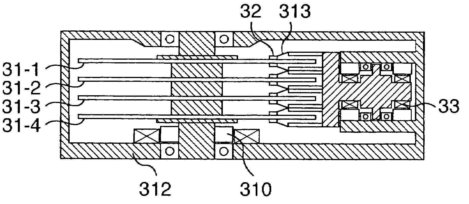
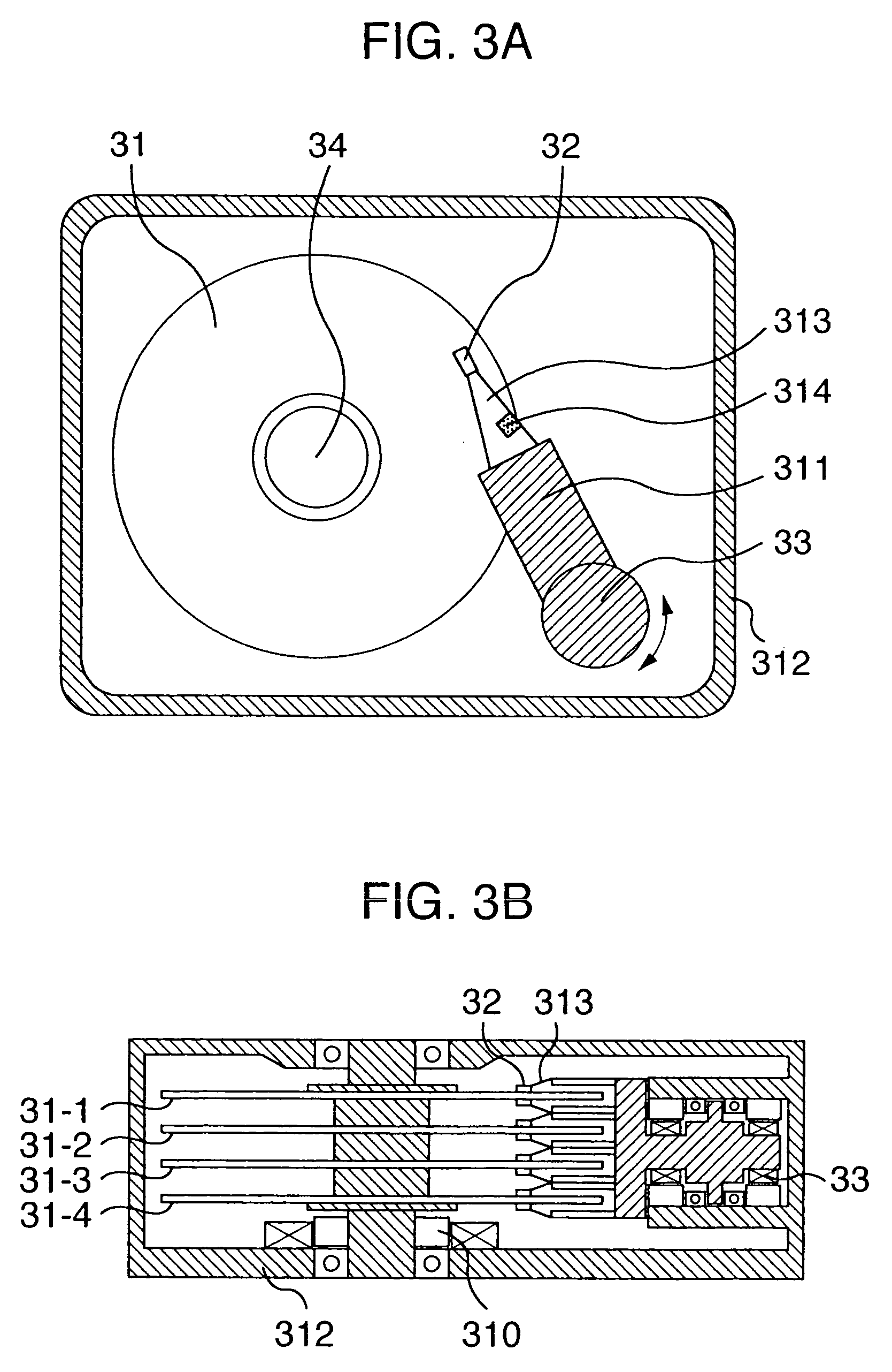
[0059]A third example of the present invention is described below by referring to FIGS. 5A and 5B, FIGS. 8A and 8B and FIGS. 3A and 3B.

[0060]As shown in FIGS. 5A and 5B, a laser chip 52, 52′ of about 0.3 mm square was mounted on a position-correcting mount 51, 51′ of the piezoelectric force type, electromagnetic force type or magnetostrictive force type. The laser chip thus mounted on the position-correcting mount was then mounted on a head slider 50, 50′ as shown in FIGS. 5A and 5B to permit adjustments so that a recording and reading element portion 53, 53′ and a laser beam position 54, 54′ are located almost on the same record track 55, 55′. An Al2O3—TiC slider of shaped rail structure with a size of 0.7×0.2 mm3 (FIG. 5A), provided with three minute projections, was used and a 3-nm thick protective film of C—N was provided on the floating surface. The volume including the laser chip (FIG. 5B) was 1.0×0.9×0.2 mm3, and the distance over which corrections are possible was 20 μm maxi...

example 4

[0072]The heads of Example 3 were also adopted as the magnetic heads of Example 1 and Example 2 and evaluated. In all of these heads of Example 3, operation of the device at areal densities of not less than 7 Gb / in2 and data transfer rates of not less than 60 MB / s were verified and characteristics equal to or better than those obtained in Example 1 and Example 2 were obtained. This was especially preferable in terms of data transfer rate. When the magnetic pole length was 55, 60, and 65 μm, recording and reading were possible at a data transfer rate of from 60 to 65 MB / s. However, when the magnetic pole length was not more than 50 μm, data transfer rate of from 66 to 70 MB / s was possible. This was especially preferable. It was ascertained by a computer simulation that it is important to reduce not only the magnetic core length l1, but also the magnetic pole length l2 because eddy currents are generated in the rear part of a magnetic pole. The R / W-IC portion was separated from the si...


PUM

PropertyMeasurementUnit
length l1aaaaaaaaaa
length l1aaaaaaaaaa
widthaaaaaaaaaa

Abstract

A magnetic recording and reading device having a transfer rate of not less than 50 MB/s includes a magnetic recording medium having an absolute value of normalized noise coefficient per recording density of not more than 2.5×10⁻⁸ (μVrms)(inch) (μm)0.5/(μVpp), and magnetic head which is mounted on an integrated circuit suspension so that a total inductance is reduced to be not more than 65nH and having a magnetic core which is not more than 35 μm of length, wherein a part of the magnetic core being formed by a magnetic film having a resistivity exceeding at least 50 μΩcm or by a multilayer film consisting of a magnetic film and an insulating film. The device also includes a fast R/W-IC having a line width of not more than 0.35 μm which is installed in a position within 2 cm from a rear end of the magnetic head.

Description

CROSS REFERENCE TO RELATED APPLICATION[0001]This is a continuation of U.S. application Ser. No. 10 / 115,917, filed Apr. 5, 2002, now U.S. Pat. No. 6,819,531, which is a continuation of U.S. application Ser. No. 09 / 725,317, filed Nov. 29, 2000, now U.S. Pat. No. 6,407,892, which is a continuation of U.S. application Ser. No. 09 / 377,189, filed Aug. 19, 1999, now U.S. Pat. No. 6,266,210, the subject matter of which is incorporated by reference herein, and is related to U.S. application Ser. No. 09 / 725,253, filed Nov. 29, 2000, now U.S. Pat. No. 6,404,605, which is a continuation of U.S. application Ser. No. 09 / 377,189, now U.S. Pat. No. 6,266,210, and is related to U.S. application Ser. No. 09 / 836,481, filed Apr. 18, 2001, now U.S. Pat. No. 6,324,035.BACKGROUND OF THE INVENTION[0002]The present invention relates to a magnetic disc device used in computers, information storage devices and so on, a magnetic storage device used in such information home appliances as digital VTRs, and a mag...

Claims


Application Information

Patent Timeline
Patent Type & Authority Patents(United States)
IPC IPC(8): G11B5/00G11B5/66G11B5/02G11B5/09G11B5/31G11B5/39G11B5/48G11B5/64G11B5/65G11B5/73G11B5/738G11B21/02
CPCB82Y10/00B82Y25/00G11B5/00G11B5/313G11B5/3909G11B5/656G11B5/7325G11B5/09G11B2005/3996G11B5/484G11B5/66G11B2005/0002G11B2005/0005G11B5/3967G11B5/73921G11B5/73911G11B5/73923G11B5/73913G11B5/73919
Inventor SHIROISHI, YOSHIHIRO
Owner WESTERN DIGITAL TECH INC
Why Eureka
Try Eureka