Systems and methods for compensating for streaks in images

a technology of system and method, applied in image enhancement, digitally marking record carriers, instruments, etc., can solve the problems of difficult to adequately calibrate streak defects in a single compensation process, and achieve the effect of reducing noise effects encountered

Active Publication Date: 2005-05-12
XEROX CORP
View PDF8 Cites 89 Cited by
  • Summary
  • Abstract
  • Description
  • Claims
  • Application Information

AI Technical Summary

Benefits of technology

[0020] In various exemplary embodiments, the systems and methods according to this invention reduce noise effects encountered during measurement by repeatedly measuring the compensation required and averaging out the noise. This is done by incrementally applying a fraction of the necessary compensation determined by the local tone reproduction curves, then reprinting and scanning the compensation pattern. The process is iterated until the additional compensation required is negligible.

Problems solved by technology

Furthermore, noise in the scanning and printing process makes is difficult to adequately calibrate the streak defects in a single compensation process.

Method used


Image

  • Systems and methods for compensating for streaks in images
  • Systems and methods for compensating for streaks in images
  • Systems and methods for compensating for streaks in images

Examples


Embodiment Construction

[0035] The compensation technique described herein can be applied to both color and monochrome image forming devices. For monochrome image forming devices, the technique is as described below. Color monochrome image forming devices operate by overlaying different color separation layers. Each color separation layer is individually compensated for using the techniques described herein. As used herein, the term “gray” indicates the amount of coverage of material between zero and 100% density on the printed surface, although in general this material may be colored.

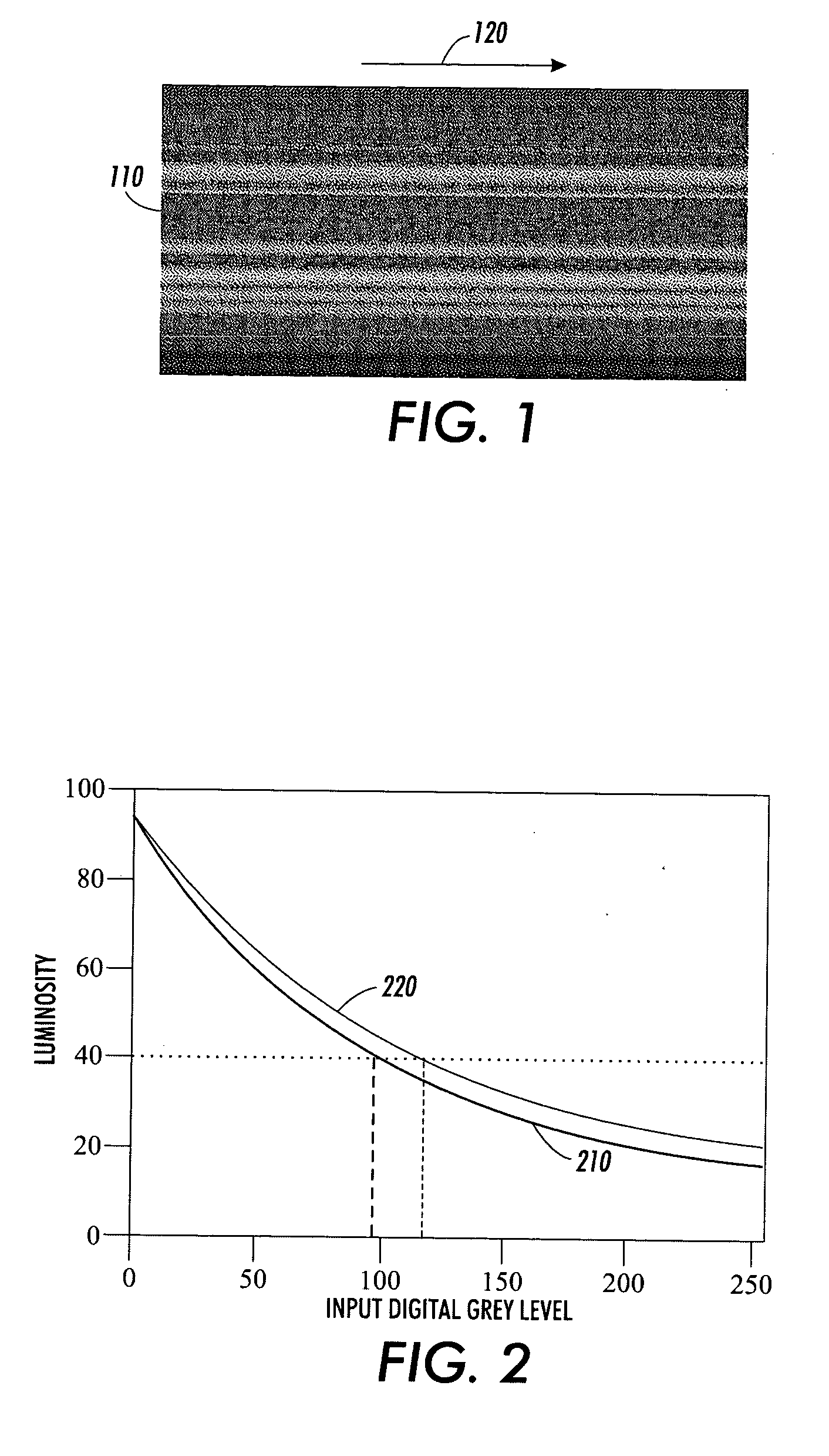
[0036] An input gray level is typically an integer between 0 and 255 that is sent to the marking engine from a computer, an input scanner or other image data source. An actual gray level is the response of a sensor measuring the gray level of the printed image. The actual gray level can be a function of distance in the cross-process direction. The desired gray level is defined as the response of the sensor to what the markin...


PUM


Abstract

Defects in an image forming system may give rise to visible streaks, or one-dimensional defects in an image that run parallel to the process direction. One known method for compensating for streaks introduces a separate tone reproduction curve for each pixel column in the process direction. A compensation pattern according to this invention has a plurality of halftone regions that are lead by, trained by, and separated by rows of fiducial marks. The fiducial marks allow the printer pixel grid and a scanning pixel grid to be correlated. The gray level in each pixel column of each gray level portion is measured and analyzed to produce a local tone reproduction curve for each pixel column and associated line width. The local tone reproduction curves are then used to compensate for the streak defect when printing.

Description

BACKGROUND OF THE INVENTION [0001] 1. Field of Invention [0002] This invention relates to systems and methods for reducing print defects in images. [0003] 2. Description of Related Art [0004] Defects in the subsystems of a xerographic, electrophotographic or similar image forming system, such as a laser printer, digital copier or the like, may give rise to visible streaks in a printed image. Streaks are primarily one-dimensional defects in an image that run parallel to the process direction. Typical defects might arise from a non-uniform LED imager, contamination of the high voltage elements in a charger, scratches in the photoreceptor surface, etc. In a uniform patch of gray, streaks and bands may appear as a variation in the gray level. In general, “gray” refers to the intensity value of any single color separation layer, whether the toner is black, cyan, magenta, yellow or some other color. [0005] One method of reducing such streaks is to design and manufacture the critical param...

Claims


Application Information

Patent Timeline
Patent Type & Authority Applications(United States)
IPC IPC(8): B41J29/46B41J29/393G03G15/00H04N1/00
CPCH04N1/4015B41J29/393
Inventor MIZES, HOWARD A.LOFTHUS, ROBERT M.
Owner XEROX CORP
Why Eureka
Try Eureka