Magnetic Recording Medium, Production Process Thereof, and Magnetic Recording and Reproducing Apparatus

a technology of magnetic recording medium and production process, which is applied in the direction of recording information storage, instruments, transportation and packaging, etc., can solve the problems of reducing the design scope of the nonmagnetic undercoat layer of the magnetic recording medium, reducing the reproduction output, and achieving high recording density. , to achieve the effect of improving the nonmagnetic undercoat layer, improving the orientation of the cr alloy, and reducing the noise of the medium

Inactive Publication Date: 2008-07-10
SHOWA DENKO KK
View PDF14 Cites 4 Cited by
  • Summary
  • Abstract
  • Description
  • Claims
  • Application Information

AI Technical Summary

Benefits of technology

[0018]As mentioned above, a Cr alloy is mainly used as the nonmagnetic undercoat layer. As a method of decreasing the medium noise by improving the nonmagnetic undercoat layer, micronization of the average crystalline particle diameter and improvement of orientation of the Cr alloy, and lattice matching with the Co alloy have been used. Since the Cr alloy used for the nonmagnetic undercoat layer has Cr as its principal component, the characteristics thereof mainly originate from the inherent characteristics of Cr. As a result, the scope for design of the nonmagnetic undercoat layer of the magnetic recording medium becomes consequently narrowed.

Problems solved by technology
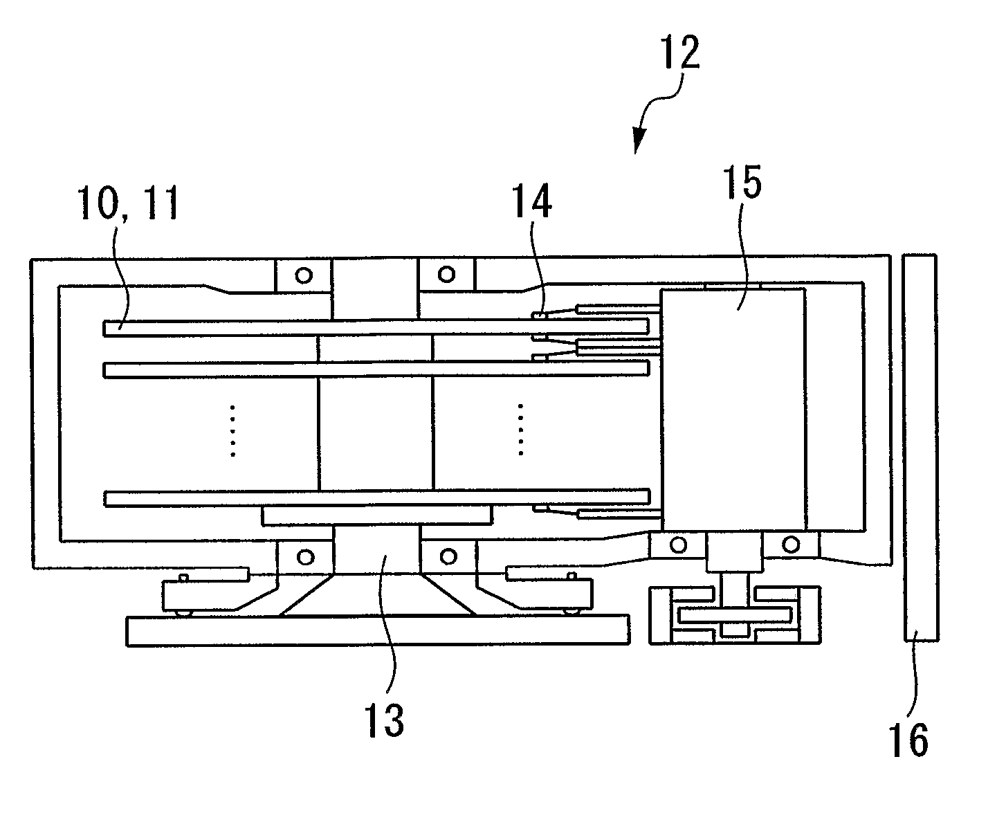
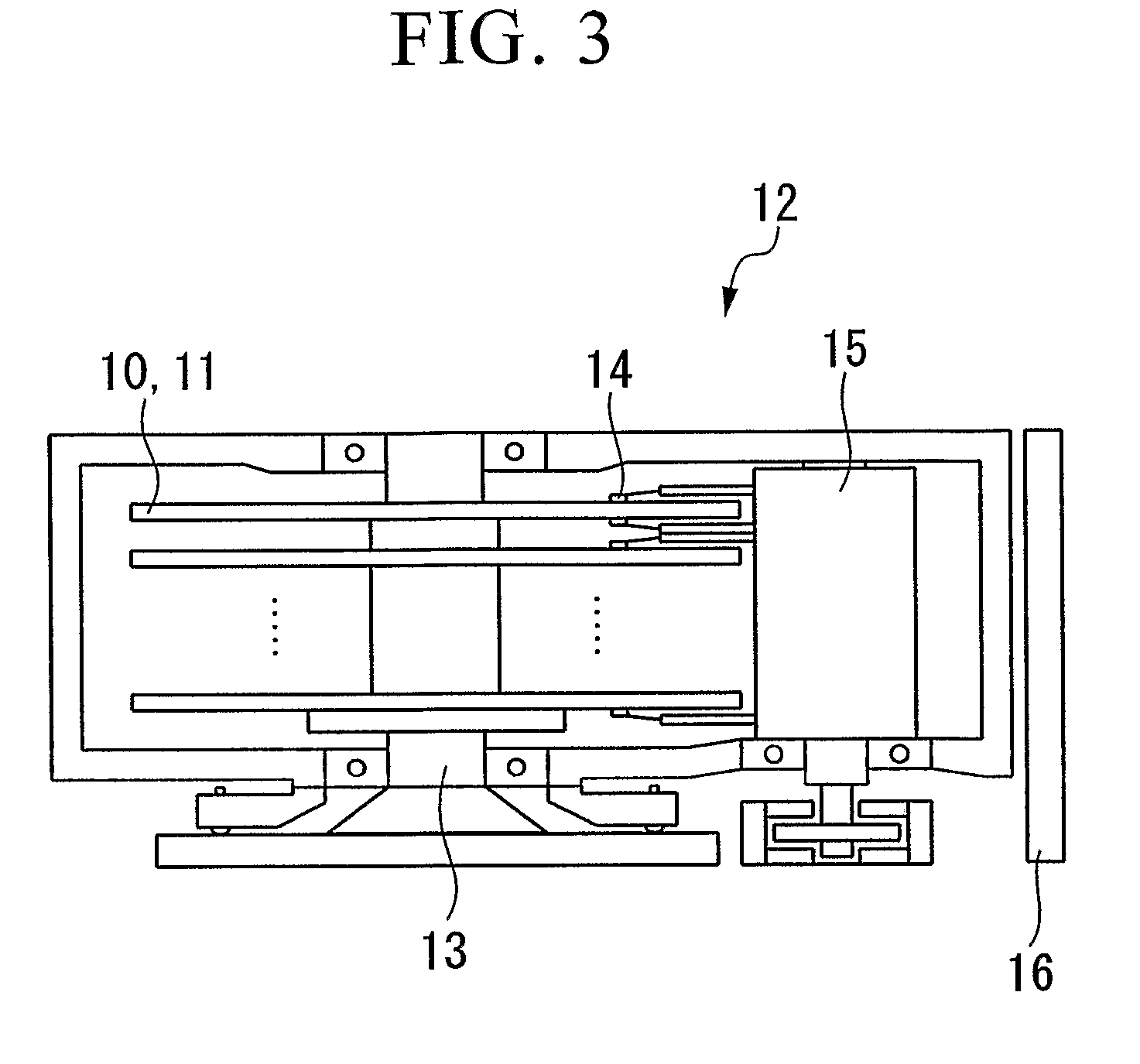
As a result, the scope for design of the nonmagnetic undercoat layer of the magnetic recording medium becomes consequently narrowed.
However, since it is difficult to make the coercive force large by use of an Al—Ni alloy, and it is difficult to make rectangularity ratio of the coercive force large by use of an Al—Co alloy, the reproduction output becomes smaller, as a result, leaving problems to realize a high recording density.
However, elemental substance of Mo or W, or alloys such as MoTi and WTi have a limit to the decrease in noise, and are unable to cope with a recording density exceeding 50 Gbits / in2.

Method used


Image

  • Magnetic Recording Medium, Production Process Thereof, and Magnetic Recording and Reproducing Apparatus
  • Magnetic Recording Medium, Production Process Thereof, and Magnetic Recording and Reproducing Apparatus
  • Magnetic Recording Medium, Production Process Thereof, and Magnetic Recording and Reproducing Apparatus

Examples


example 1

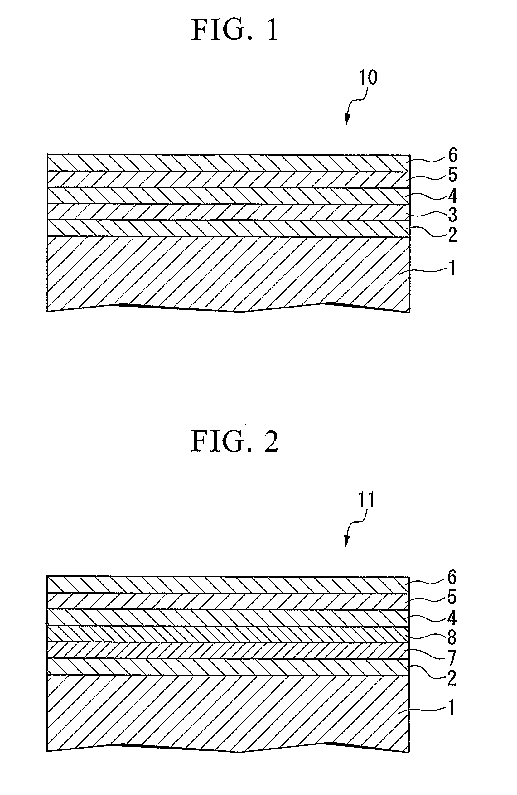
[0078]A nonmagnetic substrate 1 was used which has an NiP film (thickness 12 μm) formed by electroless deposition on the surface of a substrate made of Al (outside diameter 95 mm, inside diameter 25 mm, thickness 1.270 mm), and the surface average roughness Ra was made to be 0.5 nm by performing texture processing on the surface thereof. The nonmagnetic substrate 1 was accommodated in the chamber of a DC magnetron sputtering device (Anerva Corp., C3010), and after the chamber was evacuated to attain a vacuum level of 2×10⁻⁷ Torr (2.7×10⁻⁵ Pa), the nonmagnetic substrate 1 was heated to 250° C. A nonmagnetic undercoat layer 2 was provided on this substrate. The nonmagnetic undercoat layer 2 was prepared to have a multilayer structure, with a second undercoat layer (thickness 3 nm) comprising a WV alloy (W: 80 at %, V: 20 at %) on a first undercoat layer (thickness 2 nm) comprising Cr.

[0079]Subsequently, a nonmagnetic intermediate layer 3 (thickness 4 nm) comprising an RuCr alloy (Ru: ...

examples 2 to 29

[0083]Apart from using an alloy of a composition and film thickness as shown in Table 1 instead of the composition and film thickness of the WV alloy, which is the second nonmagnetic undercoat layer 2, the magnetic recording medium was made in the same way as for Example 1.

[0084]In the table, 1 Oe is approximately 79 A / m.

TABLE 1NONMAGNETIC UNDERCOAT LAYER1st UNDERCOAT2nd UNDERCOATNONMAGNETICLAYERLAYERINTERMEDIATE LAYERFILMFILMFILMALLOYTHICKNESSALLOYTHICKNESSALLOYTHICKNESSCOMPOSITION(nm)COMPOSITION(nm)COMPOSITION(nm)EXAMPLES 1Cr280W—20V380Ru—20Cr4EXAMPLES 2Cr280W—20V280Ru—20Cr4EXAMPLES 3Cr280W—20V580Ru—20Cr4EXAMPLES 4Cr290W—10V380Ru—20Cr4EXAMPLES 5Cr260W—40V380Ru—20Cr4EXAMPLES 6Cr270W—20V—10Al380Ru—20Cr4EXAMPLES 7Cr275W—20V—5B380Ru—20Cr4EXAMPLES 8Cr265W—20V—10Al—5B380Ru—20Cr4EXAMPLES 9Cr280Mo—20V380Ru—20Cr4EXAMPLES 10Cr290Mo—10V380Ru—20Cr4EXAMPLES 11Cr260Mo—40V380Ru—20Cr4EXAMPLES 12Cr270Mo—20V—10Al380Ru—20Cr4EXAMPLES 13Cr275Mo—20V—5B380Ru—20Cr4EXAMPLES 14Cr265Mo—20V—10Al—5B380Ru—20Cr...

example 30

[0087]A nonmagnetic substrate 1 was used, wherein an NiP film (thickness 12 μm) was formed by electroless deposition on the surface of a substrate made of Al (outside diameter 95 mm, inside diameter 25 mm, thickness 1.270 mm), and the surface average roughness Ra was made to be 0.5 nm by performing texture processing on the surface thereof. The nonmagnetic substrate 1 was accommodated in the chamber of a DC magnetron sputter device (Aneruva Corp., C3010), and after the chamber was evacuated to a vacuum attainment level of 2×10⁻⁷ Torr (2.7×10⁻⁵ Pa), the nonmagnetic substrate 1 was heated to 250° C. A nonmagnetic undercoat layer 2 was provided on this substrate. The nonmagnetic undercoat layer 2 was made to have a multilayer structure, with a second configuration layer (thickness 3 nm) comprising a WV alloy (W: 80 at %, V: 20 at %) on a first configuration layer (thickness 2 nm) comprising Cr. Next, a stabilizing layer 7 (thickness 3 nm) comprising a CoCrPtTa alloy (Co: 67 at %, Cr: 2...


PUM

PropertyMeasurementUnit
thicknessaaaaaaaaaa
thicknessaaaaaaaaaa
thicknessaaaaaaaaaa

Abstract

A magnetic recording medium is provided which is capable of higher recording density and has a higher coercive force and a lower noise. A production method of the magnetic recording medium, and a magnetic recording and reproducing apparatus are also provided. The magnetic recording medium comprises at least a nonmagnetic undercoat layer, a nonmagnetic intermediate layer, a magnetic layer, and a protective layer, which are laminated in this order on a nonmagnetic substrate, and at least one of the layers of the nonmagnetic undercoat layer is made of a WV alloy or a MoV alloy.

Description

[0001]Priority is claimed to Japanese application No. 2005-050878, filed Feb. 25, 2005, and to Japanese application No. 2005-082053, filed Mar. 22, 2005, which are incorporated herein by reference. This application also claims the benefit pursuant to 35 U.S.C. §119(e)(1) of U.S. Provisional Applications, No. 60 / 658,145 filed on Mar. 4, 2005.TECHNICAL FIELD[0002]The present invention relates to a magnetic recording medium used in hard disk drive and the like, a production method of the magnetic recording medium, and a magnetic recording and reproducing apparatus.BACKGROUND ART[0003]Hard disk drive (HDD) which are one type of magnetic recording and reproducing apparatus, have currently reached a recording density of 100 Gbits / in2, and it is said that the improvement in recording density will continue in the future at an annual rate of 30%. Consequently, the development of magnetic recording heads, and the development of magnetic recording mediums suitable for high recording density is...

Claims


Application Information

Patent Timeline
Patent Type & Authority Applications(United States)
IPC IPC(8): G11B5/33G11B5/62G11B5/84
CPCG11B5/656Y10T428/115G11B5/7325G11B5/66G11B5/7369G11B5/73911G11B5/73913G11B5/73915G11B5/73919G11B5/73921
Inventor OSAWA, HIROSHI
Owner SHOWA DENKO KK
Why Eureka
Try Eureka