Continuous production of plastic siding panels with separate shingle appearance

a production line and plastic technology, applied in the field of vinyl siding panels, can solve problems such as damage to the structure, and achieve the effect of realistic appearan

Inactive Publication Date: 2005-07-07
TAPCO INTERNATIONAL CORPORATON
View PDF18 Cites 11 Cited by
  • Summary
  • Abstract
  • Description
  • Claims
  • Application Information

AI Technical Summary

Benefits of technology

[0004] One advantage of the subject invention is that the siding panel has a realistic appearance that is enhanced by the projection portion extending at different amounts beyond the horizontal plane. The projection portion gives the siding panel a jagged appearance which is more similar to actual shake siding. Another advantage of the projection portion is that when the siding panels are fastened to a structure, moisture is not able to get behind the siding panels because the moisture is not able to follow the projection portion. Whereas the moisture does travel along the generally flat bottom of the prior art siding panels and damages the structure. Therefore, it is advantageous that the subject invention does not allow the moisture to travel along the projection portion and behind the siding panels.

Problems solved by technology

Whereas the moisture does travel along the generally flat bottom of the prior art siding panels and damages the structure.

Method used


Image

  • Continuous production of plastic siding panels with separate shingle appearance
  • Continuous production of plastic siding panels with separate shingle appearance
  • Continuous production of plastic siding panels with separate shingle appearance

Examples


Embodiment Construction

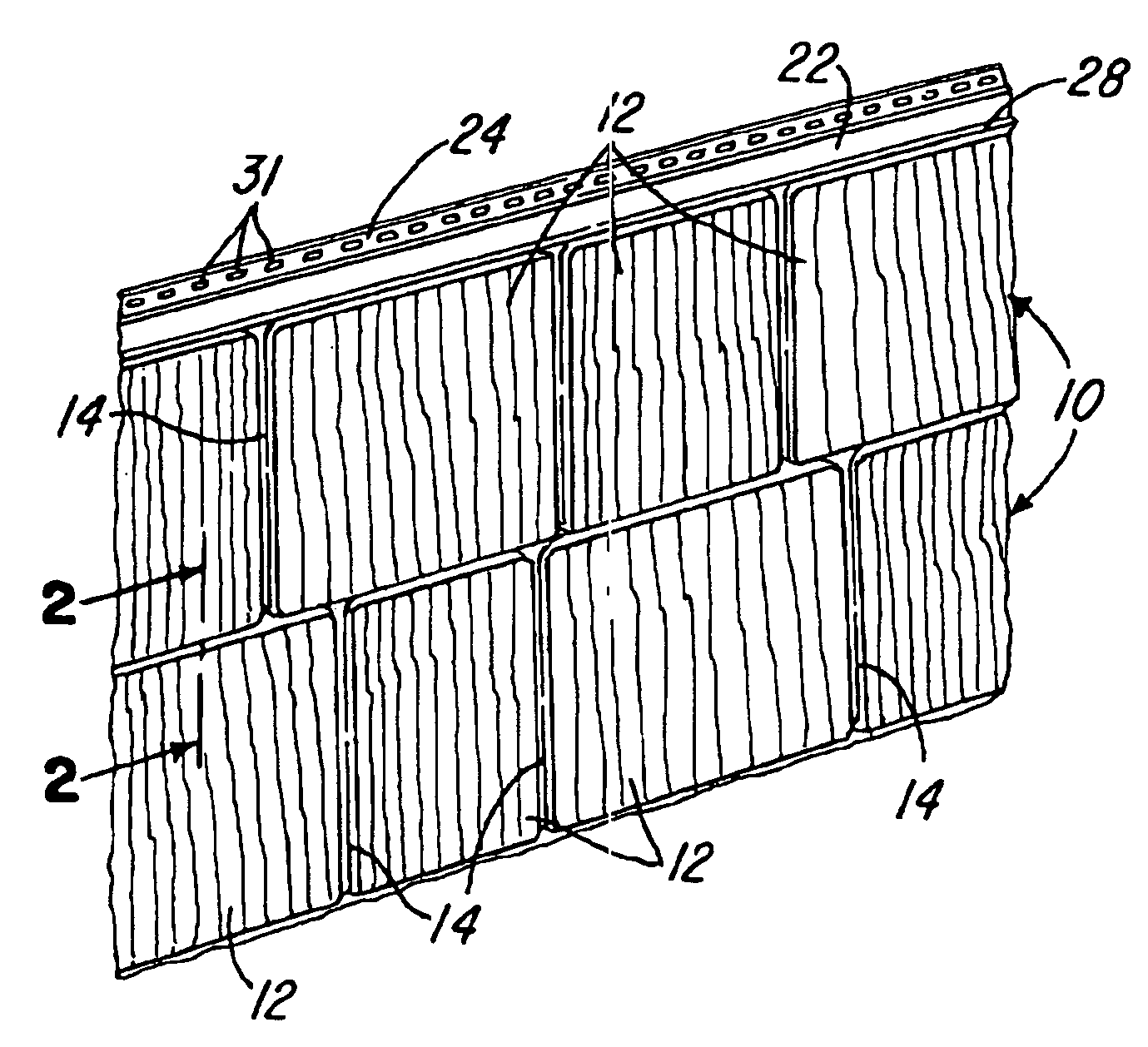
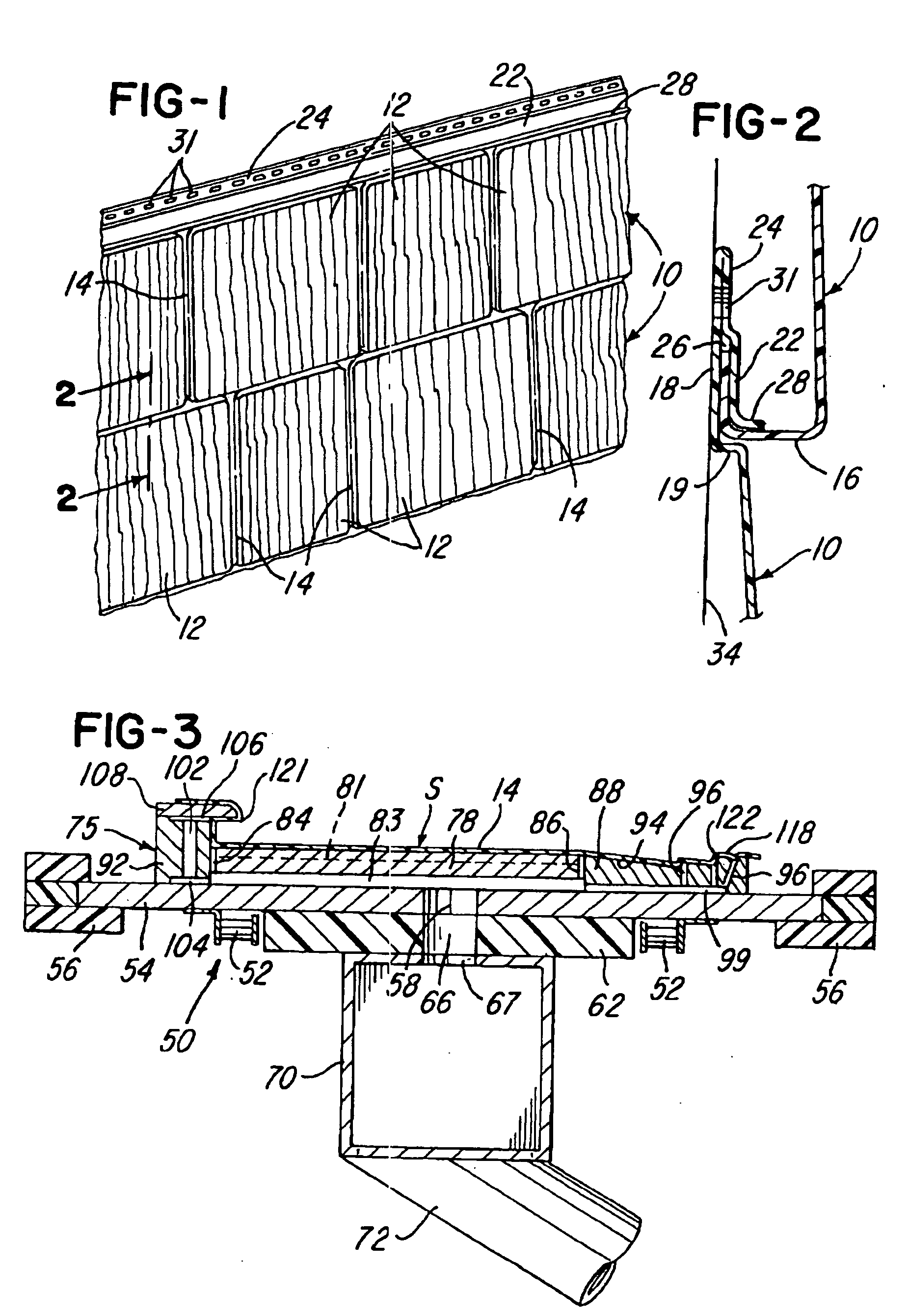
[0029]FIG. 1 illustrates portions of two elongated siding panels 10 connected together as shown in FIG. 2, and each siding panel has a length of about five feet. Each siding panel is formed from a sheet of rigid plastics material such as polyvinylchloride or “vinyl” and includes a series of ten generally rectangular shingle panels 12 each having a different and distinct wood grain appearance. The shingle panels 12 are integrally connected by flat recessed strip portions 14 defining grooves, and each panel 10 has a longitudinally extending hook-shaped lower portion 16 (FIG. 2). Each panel 10 also has a longitudinally extending upper flange portion 18 which extends from a step or shoulder portion 19 and is integrally connected to a folded-over flange portion 22.

[0030] The folded-over flange portion 22 cooperates with the flange portion 18 to form a double wall nailing flange 24 and a slot or groove 26 for receiving and retaining the hook-shaped lower edge portion 16 of the above over...


PUM

PropertyMeasurementUnit
angleaaaaaaaaaa
lengthaaaaaaaaaa
C-shapeaaaaaaaaaa

Abstract

A method and an apparatus for continuously producing elongated siding panels is disclosed. The apparatus includes a conveyor, a plurality of mold plates, and a die for extruding a sheet of material onto the mold plates. The mold plates are formed of a rigid material and positioned adjacent one another and supported by the conveyor for forming the elongated siding panels. Each of the mold plates has an upper edge portion and a lower edge portion with an intermediate portion therebetween. The intermediate portion has an aesthetic pattern for imparting the pattern to the sheet of material with the adjacent mold plates having different aesthetic patterns. The lower edge portion has a lower leg extending substantially perpendicular from the intermediate portion defining a horizontal plane and a projection portion between the lower edge portion and the intermediate portion extends beyond the horizontal plane for imparting a jagged pattern to the intermediate portion.

Description

CROSS-REFERENCES TO RELATED APPLICATIONS [0001] This application is continuation-in-part of U.S. patent application Ser. No. 10 / 689,137, filed on Oct. 20, 2003, which is a divisional of U.S. Pat. No. 6,635,218, issued on Oct. 21, 2002, which is a continuation-in-part of U.S. patent application Ser. No. 09 / 315,317, filed May 20, 1999, which claims the benefit of U.S. Provisional Patent Application Ser. No. 60 / 086,378 filed on May 22, 1998.BACKGROUND OF THE INVENTION [0002] In the production of vinyl siding panels having the appearance of rough-sawn cedar shake shingles, for example, as disclosed in U.S. Pat. Nos. 3,593,479 and 5,455,099, it is known to injection mold the panel or vacuum-form a precut sheet and then trim and punch and form the edge portions of the sheet, to form a hook-shaped lower portion along the panel and an upper portion which defines a groove and forms a nailing flange. It is also known to extrude or form a flat sheet of plastics material and then direct the she...

Claims


Application Information

Patent Timeline
Patent Type & Authority Applications(United States)
IPC IPC(8): B29C48/00B29C48/07B29C48/13B29C48/355B29C51/10B29C51/24B29C51/34B29C53/02E04D1/26E04F13/08E04F13/18
CPCB29C47/00E04F13/185B29C47/0033B29C47/0038B29C47/0054B29C47/0066B29C51/10B29C51/24B29C51/34B29C53/02B29C2791/001B29C2791/006B29C2793/00B29C2793/009B29K2905/02B29K2995/0072B29L2031/108E04D1/265E04F13/0864B29C47/0019B29C48/00B29C48/07B29C48/13B29C48/001B29C48/0017B29C48/0022
Inventor KING, DANIEL W.
Owner TAPCO INTERNATIONAL CORPORATON
Why Eureka
Try Eureka