Internal combustion engine with hydraulic device for adjusting the rotation angle of a camshaft in relation to a crankshaft

a technology of hydraulic device and internal combustion engine, which is applied in the direction of machines/engines, valve drives, mechanical equipment, etc., can solve the problems of large manufacturing cost of sintered components by material removal process, undesired external oil leakage, etc., and achieves the effect of reducing the wall thickness of the sidewalls of the stator, reducing the size of the hydraulic device, and facilitating manufacturing

Active Publication Date: 2005-07-07
SCHAEFFLER TECH AG & CO KG
View PDF1 Cites 7 Cited by
  • Summary
  • Abstract
  • Description
  • Claims
  • Application Information

AI Technical Summary

Benefits of technology

[0019] According to another feature of the present invention, the cutouts between the sidewalls may be filled with insets of plastic or metal to thereby further reinforce and stiffen the pot-shaped structure.
[0020] According to another feature of the present invention, an angle limitation unit may be provided to restrict the rotation angle of the rotor. In this way, the wall thickness of the sidewalls of the stator can further be reduced by preventing the vanes of the rotor to impact the sidewalls in their respective end positions and thereby apply pressure. The angle limitation unit may be realized by forming t...

Problems solved by technology

As a result, the hydraulic device is very massive.
In addition, manufacturing costs for making the sintered components by the material removal process are extensive, and undesired external oil leaks can be experienced as a consequence of the porosity of the sintered components.
Another reason for making the components of hydraulic devices heavy and massive is the belief that thin wall thicknesses in sintering metallurgy would cause problems as far as density distribution, strength and stiffness are concerned, especially when the wall thickness fluctuates, and that complex shapes with different fill heights can normally be realized only by using expensive slides in the tool.
Hydrau...

Method used


Image

  • Internal combustion engine with hydraulic device for adjusting the rotation angle of a camshaft in relation to a crankshaft
  • Internal combustion engine with hydraulic device for adjusting the rotation angle of a camshaft in relation to a crankshaft
  • Internal combustion engine with hydraulic device for adjusting the rotation angle of a camshaft in relation to a crankshaft

Examples


first embodiment

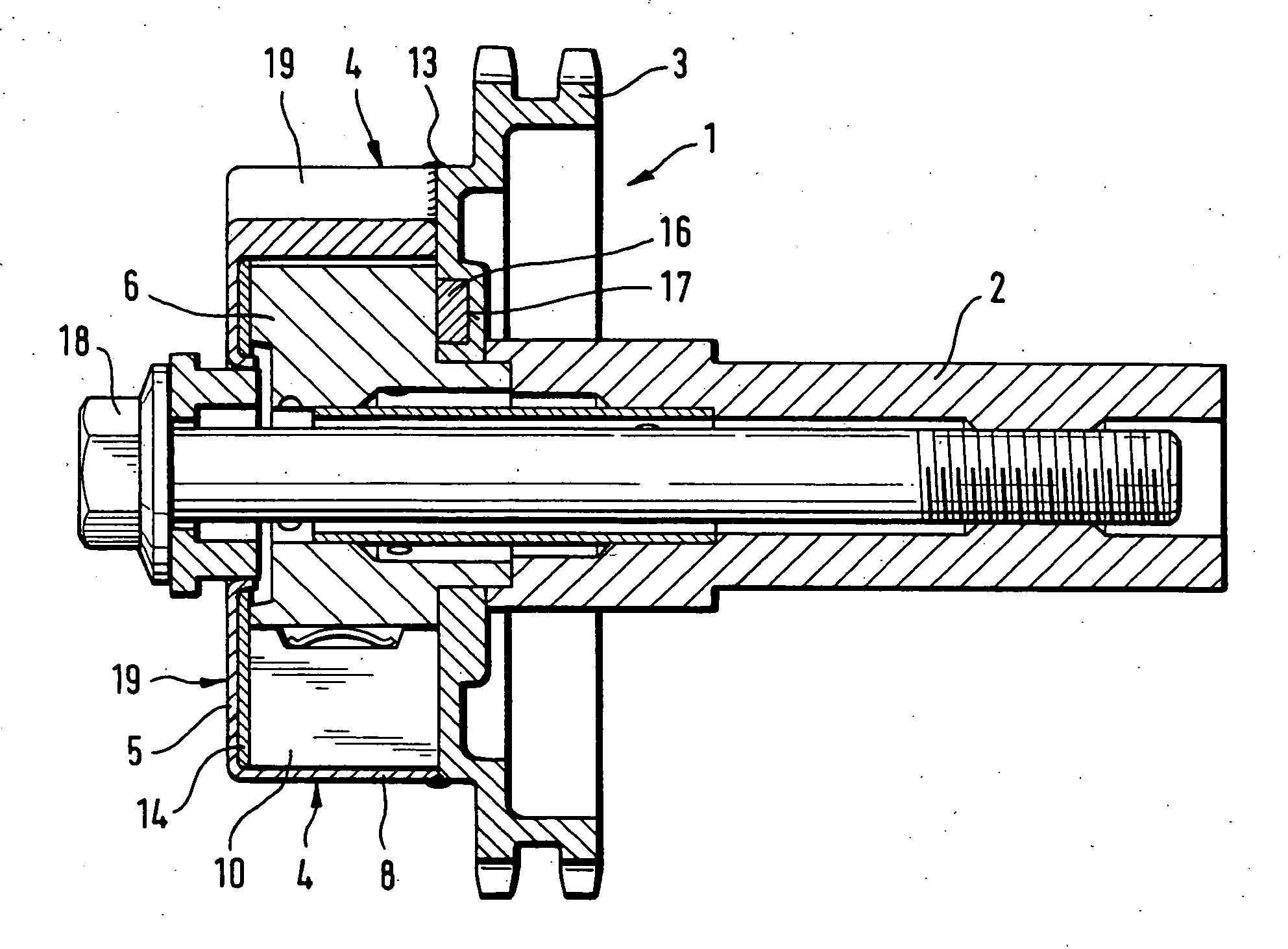
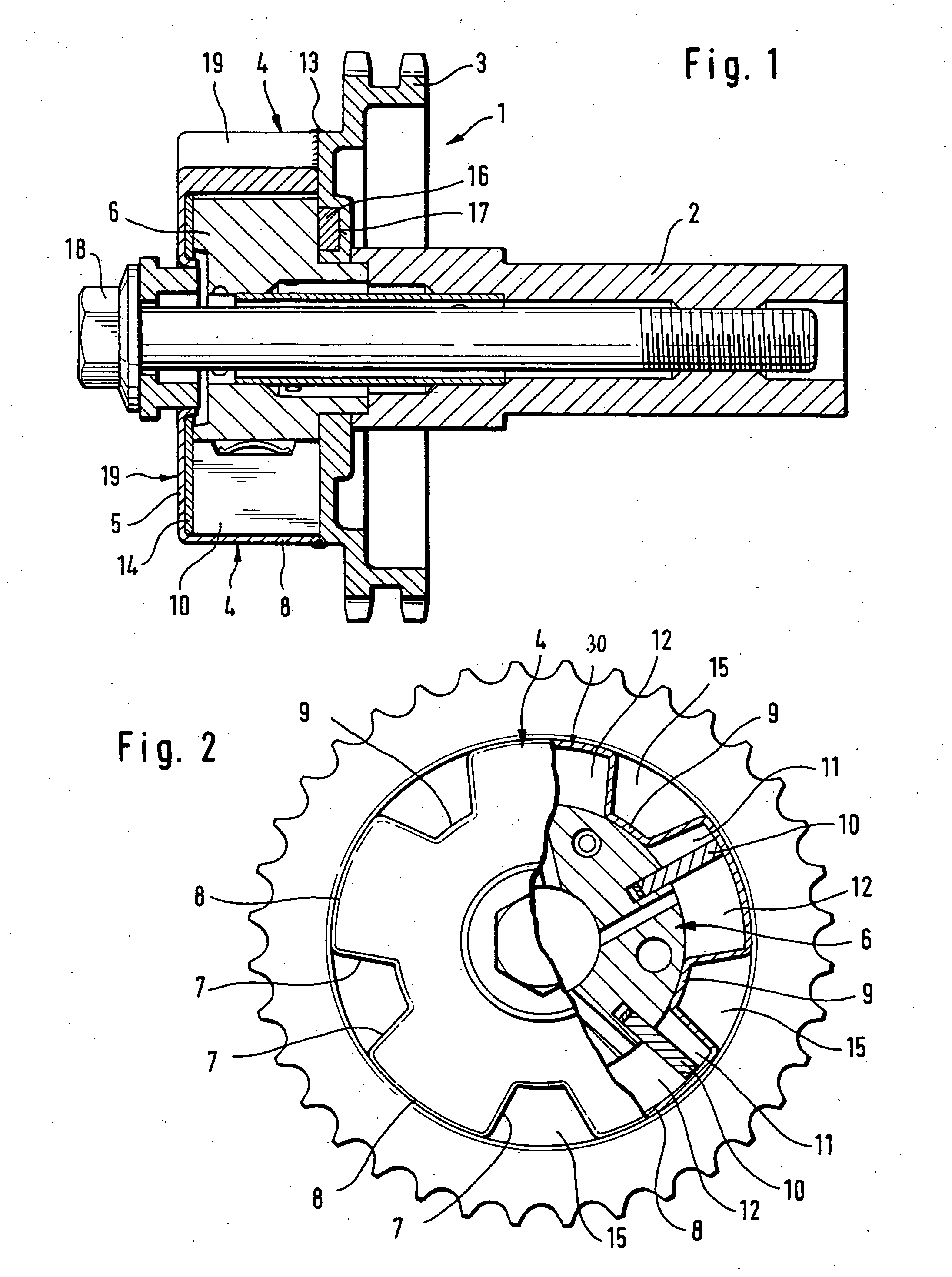
[0029] Turning now to the drawing, and in particular to FIG. 1, there is shown a longitudinal section of a hydraulic device according to the present invention, generally designated by reference numeral 1, for adjusting the rotation angle of a camshaft 2 in relation to a crankshaft (not shown). The hydraulic device 1 is implemented as a hydraulic actuator for varying the opening and closing times of gas exchange valves of an internal combustion engine and is operated by a timing pulley 3 which may be connected via a not shown chain to the crankshaft. The hydraulic device 1 includes essentially a tubular stator 4, which is firmly secured to the timing pulley 3, and a rotor 6, which is connected in fixed rotative engagement via an axial central screw 18 to the camshaft 2 and is constructed in the form of a vane wheel having vanes 10. The stator 4 is constructed in one piece with an end wall 5 to thereby exhibit overall a pot-shaped structure, generally designated by reference numeral 1...

second embodiment

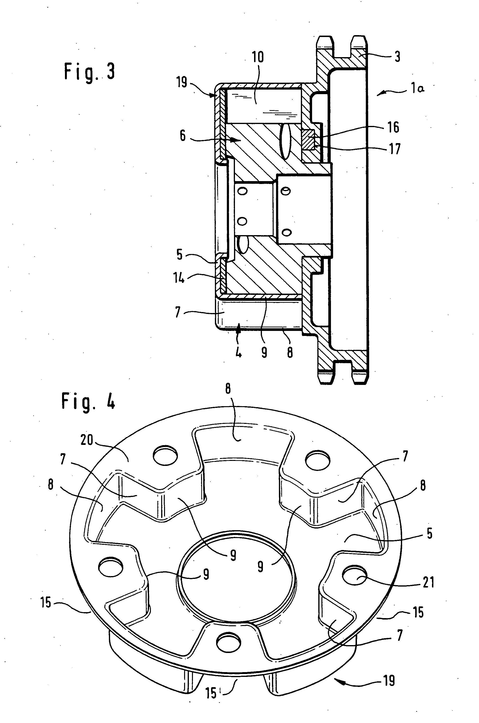
[0035] Referring now to FIG. 3, there is shown a longitudinal section of a hydraulic device for rotation angle adjustment according to the present invention, generally designated by reference numeral 1a. Parts corresponding with those in FIG. 1 are denoted by identical reference numerals and not explained again. The description below will center on the differences between the embodiments. In this embodiment, provision is made for a sealing disk or washer 14 which is placed inside the pot 19 and rests against the end wall 5 on the camshaft proximal side. The washer 14 is hereby configured to conform to the inner contour of the pot 19. The provision of the washer 14 is intended for those situations in which the transition from the stator 4 to the end wall 5 of the pot 19 does no define a precise right angle so as to reduce leakage losses.

[0036]FIG. 4 is a perspective view of a modified pot 19 for a hydraulic device for rotation angle adjustment according to the present invention. The ...


PUM


Abstract

A hydraulic device in an internal combustion engine for adjusting a rotation angle of a camshaft in relation to a crankshaft includes a tubular stator and a rotor connected in fixed rotative engagement with the camshaft and having plural vanes in spaced apart relationship to define pressure chambers on both sides of the vanes. The stator is connected in fixed rotative engagement with a crankshaft-drive timing pulley and formed in single-piece construction with an end wall to thereby exhibit a pot-shaped structure. The pot is made without material removal from a sheet metal part and constructed to define with the rotor vanes the pressure chambers. Pressure medium is supplied to or purged from the pressure chambers to selectively adjust the position of the rotor in relation to the stator and thereby the position of the camshaft in relation to the crankshaft.

Description

CROSS-REFERENCES TO RELATED APPLICATIONS [0001] This application claims the priority of German Patent Application, Serial No. 103 59 068.4, filed Dec. 16, 2003, pursuant to 35 U.S.C. 119(a)-(d). BACKGROUND OF THE INVENTION [0002] The present invention relates, in general, to an internal combustion engine, and more particularly to a hydraulic device of an internal combustion engine to adjust the rotation angle of a camshaft in relation to a crankshaft. [0003] Nothing in the following discussion of the state of the art is to be construed as an admission of prior art. [0004] German patent publication no. DE 101 34 320 A1 describes a hydraulic device for adjusting the rotation angle of a camshaft in relation to a crankshaft of an internal combustion engine. The device includes a rotor, which is configured in the form of a vane wheel secured to the camshaft by a central fastening screw, and a stator which is closed in fluid-tight manner by an end wall, which forms part of a housing in su...

Claims


Application Information

Patent Timeline
IPC IPC(8): F01L1/34F01L1/344
CPCF01L1/3442F01L1/34F01L2250/02F02B67/06Y02T10/12
Inventor WIERL, ULRICHKOHRS, MIKEOTTERSBACH, RAINERAUCHTER, JOCHEN
Owner SCHAEFFLER TECH AG & CO KG
Why Eureka
Try Eureka