
Liquid spray gun with manually separable portions

a liquid spray gun and separable portion technology, applied in the direction of spraying apparatus, spray nozzle, liquid spraying apparatus, etc., can solve the problem of adding difficulty to the removal process, and achieve the effect of easy disassembly

Active Publication Date: 2005-07-07
3M INNOVATIVE PROPERTIES CO
View PDF26 Cites 102 Cited by
  • Summary
  • Abstract
  • Description
  • Claims
  • Application Information

AI Technical Summary

Benefits of technology

[0003] The present invention provides a liquid spray gun generally of the type described above that is more easily disassembled between successive uses.
[0006] The platform portion can be reusable (i.e., made of metal), and the nozzle and air cap portions can be molded of a polymeric material. The molded air cap and nozzle portions can be sufficiently inexpensive that they can be discarded rather than cleaned for some applications.
[0007] The passageways on the horns opening through the outlet apertures that direct high velocity air flowing through the second air passageway against opposite sides of a stream of liquid formed by air flowing through the first air passageway to reshape that generally conical stream of liquid into a wide elongate stream can have a greater width in a direction at a right angle to the axis than depth in a direction parallel to the axis (e.g., the outlet apertures can be generally rectangular). Such a shape has been found to form a liquid stream that is very uniform in width and in the amount of liquid delivered per unit time along its length to facilitate uniform application of the liquid to a surface.

Problems solved by technology

In the spray guns described in those U.S. patents typically the nozzle portions can be removed from the platform portions, however the means for mounting the nozzle portions on the platform portions includes attachment members such as threaded nuts that must be removed with a tool such as a wrench, thereby adding difficulty to that removal process.

Method used


Image

  • Liquid spray gun with manually separable portions
  • Liquid spray gun with manually separable portions
  • Liquid spray gun with manually separable portions

Examples


Embodiment Construction

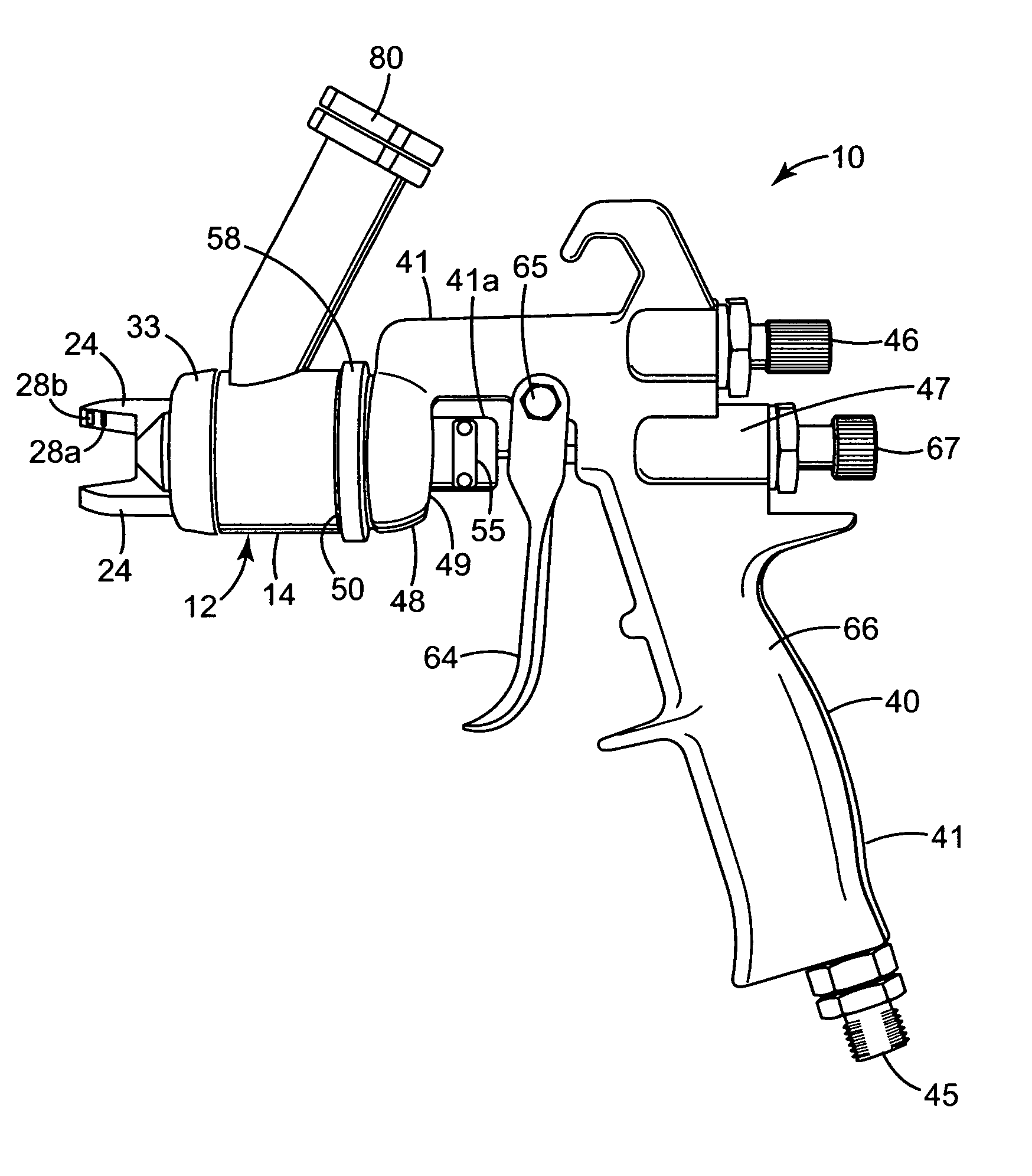
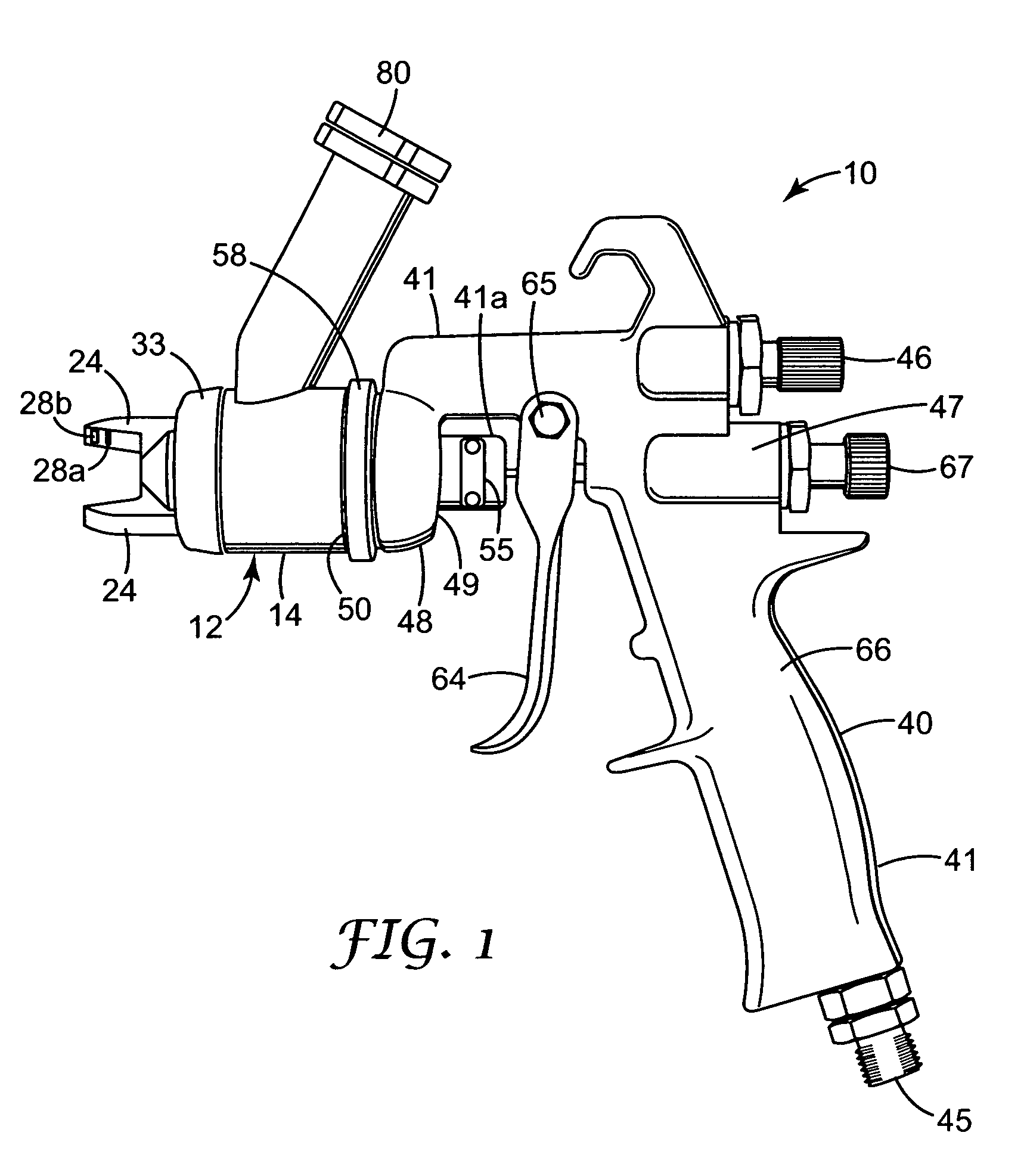
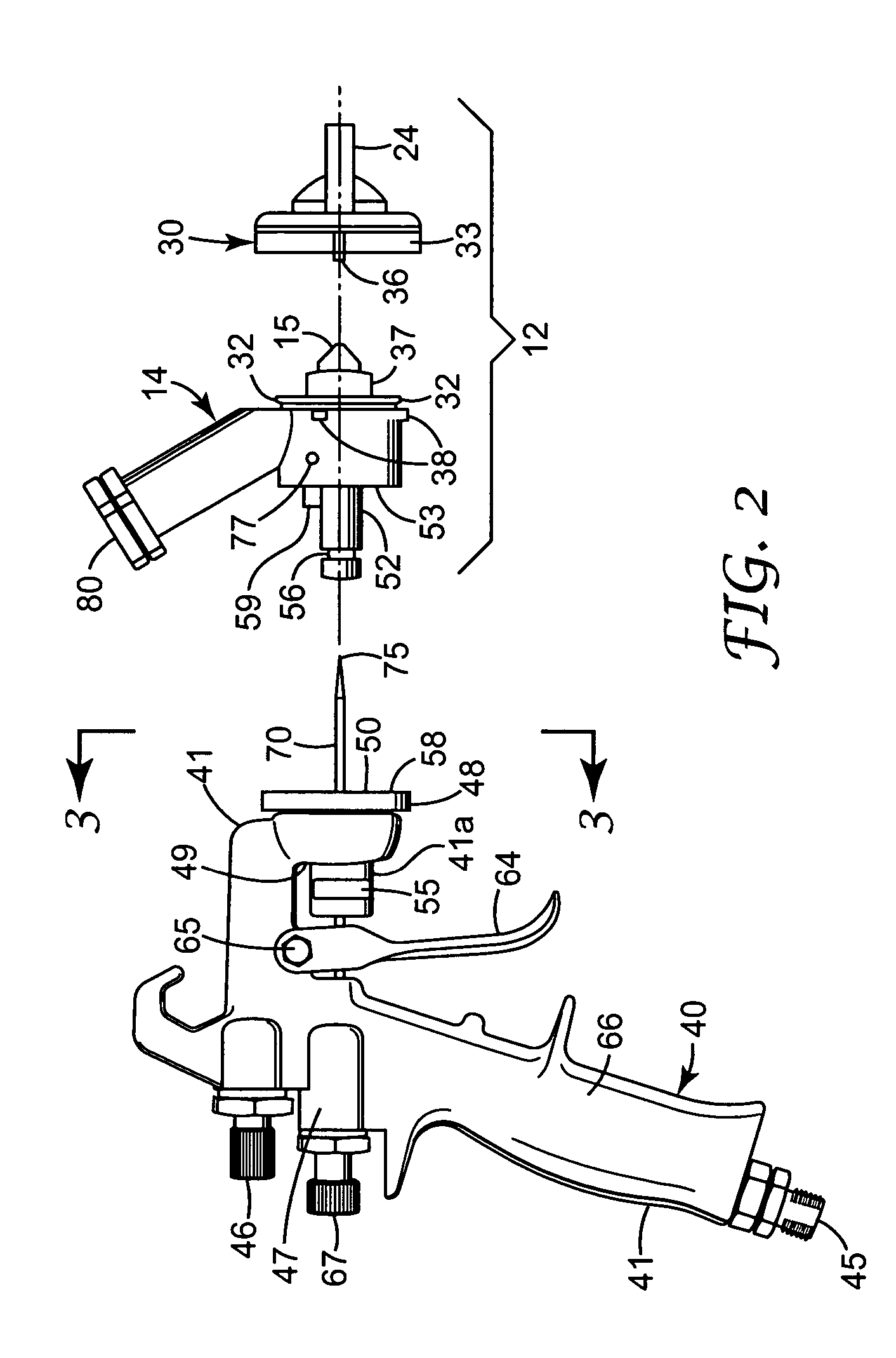
[0025] Referring now to the drawing there is illustrated a liquid spraying device or spray gun 10 according to the present invention. Generally, the liquid spray gun 10 comprises a body assembly 12 including a nozzle portion 14 with an outlet end 15. The nozzle portion 14 has a liquid passageway 16 extending from an inlet end 17 to an outlet end 18 opening through the outlet end 15 of the nozzle portion 14. The body assembly 12 also has a first air passageway 20 extending from an inlet end 21 to an outlet end 22 at the outlet end 15 of the nozzle portion 14. The outlet end 22 of the first air passageway 20 extends around the outlet end 18 of the liquid passageway 16 and is shaped to direct air under greater than atmospheric pressure against liquid flowing out of the outlet end 18 of the liquid passageway 16 to propel liquid flowing out of the liquid passageway 16 away from the outlet end 15 of the nozzle portion 14 while shaping the liquid into a generally conical stream about an ax...


PUM


Abstract

The present invention provides a liquid spray gun with several improved features, including (1) a molded polymeric possibly disposable body assembly through which passes liquid sprayed by the spray gun that is manually releasable from a metal platform portion of the spray gun through which air is fed to passageways through the body assembly to spray the liquid; (2) non-cylindrical air passageways on air horns that provide improved shape and uniformity for the wide elongate stream of liquid formed by the spray gun, and (3) an air cap portion of the body assembly mounted for manual rotation on a nozzle portion of the body assembly between positions defined by stops and retained at those positions by friction.

Description

FIELD OF THE INVENTION [0001] This invention relates to liquid spray guns of the type comprising a body assembly including a nozzle portion having a liquid passageway extending to an outlet end opening through an outlet end of the nozzle portion, the body assembly having a first air passageway having an outlet end at the outlet end of the nozzle portion that extends around the outlet end of the liquid outlet passageway and is shaped to direct air under greater than atmospheric pressure against liquid flowing out of the outlet end of the liquid outlet passageway to propel the liquid away from that outlet end while shaping the liquid into a generally conical stream about an axis; the body assembly including horns projecting past the outlet end of the nozzle on opposite sides of the axis, and also having a second air passageway extending to outlet passageways and apertures spaced along the horns from the outlet end of the nozzle portion and facing opposite sides of the axis, which outl...

Claims


Application Information

Patent Timeline
Patent Type & Authority Applications(United States)
IPC IPC(8): B05B7/02B05B7/06B05B7/08B05B7/12B05B7/24
CPCB05B7/02B05B7/066B05B7/2478B05B7/083B05B7/1209B05B7/0815
Inventor BLETTE, RUSSELL E.FREDERICKSON, FRANKLYN L.JOSEPH, STEPHEN C.P.QIBLAWI, JAMEEL R.
Owner 3M INNOVATIVE PROPERTIES CO
Features
  • Generate Ideas
  • Intellectual Property
  • Life Sciences
  • Materials
  • Tech Scout
  • Unparalleled Data Quality
  • Higher Quality Content
  • 60% Fewer Hallucinations
Learn More