
Wave detection methods and apparatus

a wave detection and wave technology, applied in the field of wave detection, can solve the problems of high cost of systems that incorporate this technology, inconvenient operation, and inability to meet the sensitivity requirements of many applications,

Inactive Publication Date: 2005-07-07
PRATHER DENNIS W +2
View PDF5 Cites 3 Cited by
  • Summary
  • Abstract
  • Description
  • Claims
  • Application Information

AI Technical Summary

Benefits of technology

[0005] The present invention is embodied in methods and apparatus for detecting waves. The waves are detected by modulating an optical carrier signal having a carrier signal frequency component at a carrier frequency with wave signals at one or more detection frequencies, optically removing the carrier signal frequency component from the modulated optical carrier signal, and detecting an energy level of the modulated optical carrier signal after removal of the carrier signal frequency component, the energy level indicative of the presence of the wave signals.

Problems solved by technology

Systems that incorporate this technology typically cost in excess of $50K, which is cost prohibitive for many applications.
Antenna-coupled microbolometers approaches, while generally less expensive, typically have noise-equivalent-powers (NEP) in the 10s of pico-watts, which does not satisfy sensitivity requirements for many applications.

Method used


Image

  • Wave detection methods and apparatus
  • Wave detection methods and apparatus
  • Wave detection methods and apparatus

Examples


Embodiment Construction

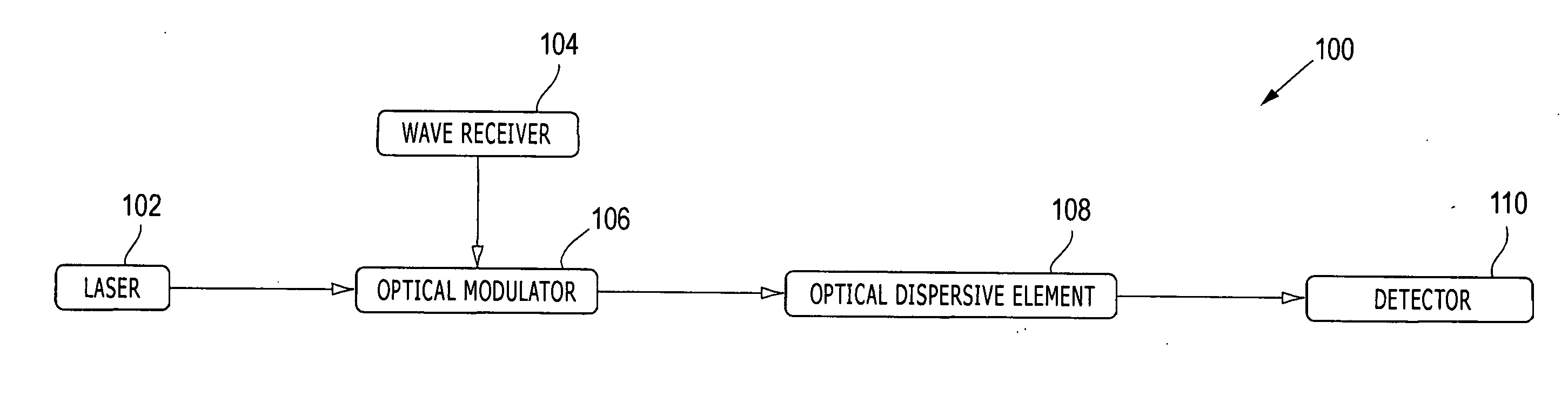
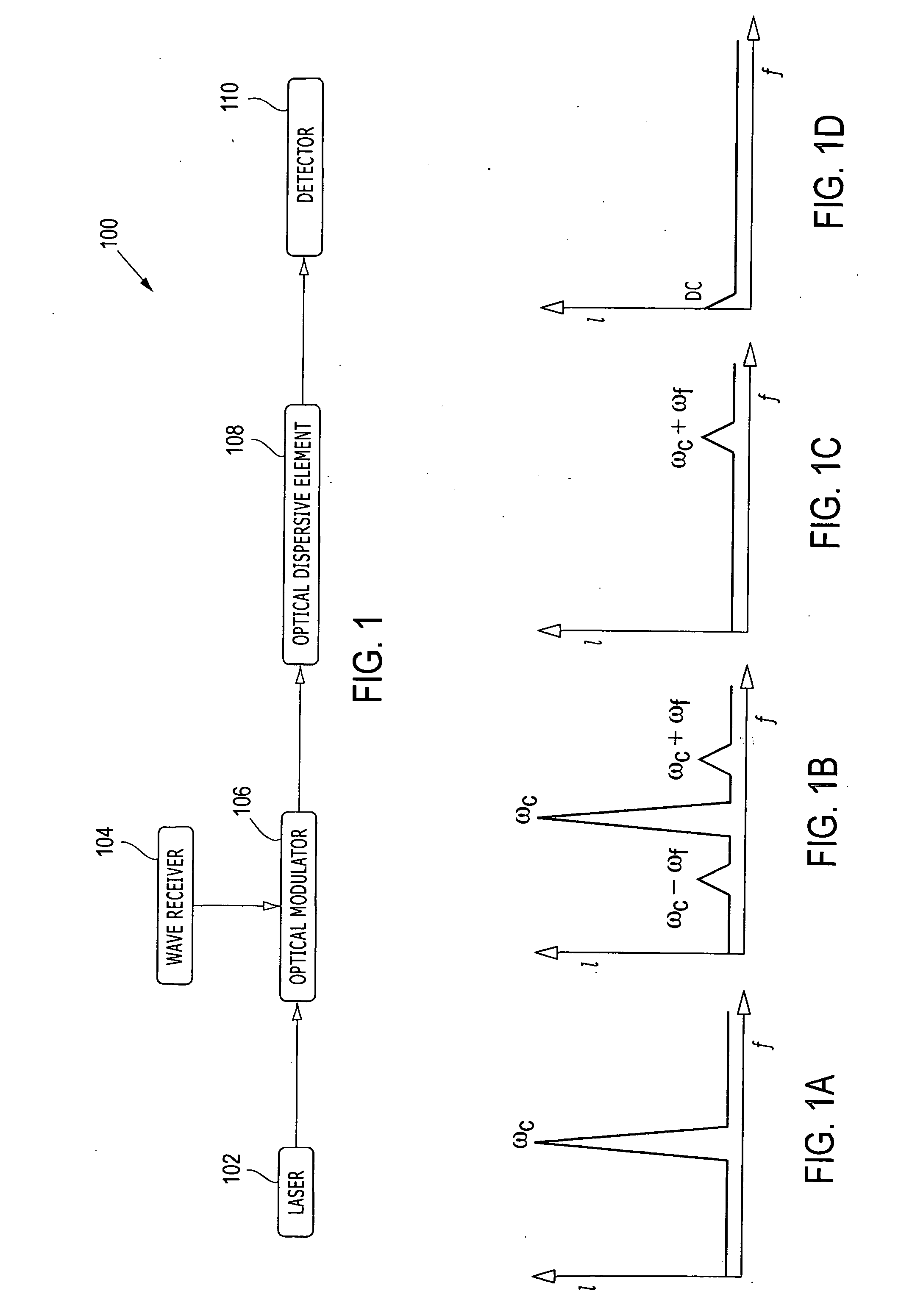
[0012]FIG. 1 depicts a block diagram of a wave detector 100 for use in providing an overview of the present invention. The wave detector 100 is described below with reference to FIGs. 1A-1D, which conceptually illustrates photon intensity (I) versus frequency (f) at various positions within the wave detector 100.

[0013] In general overview, a laser 102 generates an optical carrier signal having a carrier frequency, ωc, which is illustrated in FIG. 1A. A wave receiver 104 receives one or more wave signals at one or more corresponding detection frequencies, ωf, e.g., millimeter-waves and / or microwaves. A optical modulator 106 is configured to modulate the optical carrier signal with the desired wave signals, which transfers energy from the desired wave signals into sidebands of the optical carrier signal, e.g., at ωc+ωf and ωc−ωf, which is illustrated in FIG. 1B. An optical dispersive element 108 removes the carrier signal frequency component (and optionally one of the sidebands) from...


PUM


Abstract

Methods and apparatus for detecting waves are disclosed. The waves are detected by modulating an optical carrier signal having a carrier signal frequency component at a carrier frequency with wave signals at one or more detection frequencies, optically removing the carrier signal frequency component from the modulated optical carrier signal, and detecting an energy level of the modulated optical carrier signal after removal of the carrier signal frequency component, the energy level indicative of the presence of the wave signals.

Description

CROSS-REFERENCE TO RELATED APPLICATIONS [0001] This application claims the benefit of Provisional Patent Application No. 60 / 512,891 filed Oct. 21, 2003, entitled “Wave Detector,” incorporated herein by reference.FIELD OF THE INVENTION [0002] The present invention relates to the field of wave detection and, more particularly, to methods and apparatus for detecting waves such as millimeter-waves and microwaves. BACKGROUND OF THE INVENTION [0003] Millimeter-waves and microwaves are typically detected using substantially electronic or antenna-coupled microbolometer approaches. In an electronic approach, monolithic microwave integrated circuits (MMICs) are used for filtering, amplification, and mixing at frequencies approaching 100 GHz. Systems that incorporate this technology typically cost in excess of $50K, which is cost prohibitive for many applications. Antenna-coupled microbolometers approaches, while generally less expensive, typically have noise-equivalent-powers (NEP) in the 10s...

Claims


Application Information

Patent Timeline
Patent Type & Authority Applications(United States)
IPC IPC(8): G01R29/08H01Q9/27H04B10/04
CPCH01Q9/27G01R29/0864
Inventor PRATHER, DENNIS W.DELIWALA, SHRENIKSCHUETZ, CHRISTOPHER
Owner PRATHER DENNIS W
Learn More