Adjustable range of motion limiter

a range of motion limiter and adjustable technology, applied in the field of orthosis with dual-adjustable range of motion limiters, can solve the problems of wearers requiring a greater range of motion, parts that are not easily replaced by wearers, and difficulty in manufacturing, and achieve the effect of convenient and inexpensive manufacture and quiet us

Inactive Publication Date: 2005-07-07
CURRIER MARK R
View PDF11 Cites 6 Cited by
  • Summary
  • Abstract
  • Description
  • Claims
  • Application Information

AI Technical Summary

Benefits of technology

[0028] The present invention achieves those and other objectives by providing a comfortable ankle-foot orthosis that is both strong and lightweight

Problems solved by technology

One problem with this device is that the adjusting mechanism has multiple parts making it difficult and expensive to manufacture.
Another problem with this device is t

Method used


Image

  • Adjustable range of motion limiter
  • Adjustable range of motion limiter
  • Adjustable range of motion limiter

Examples


Embodiment Construction

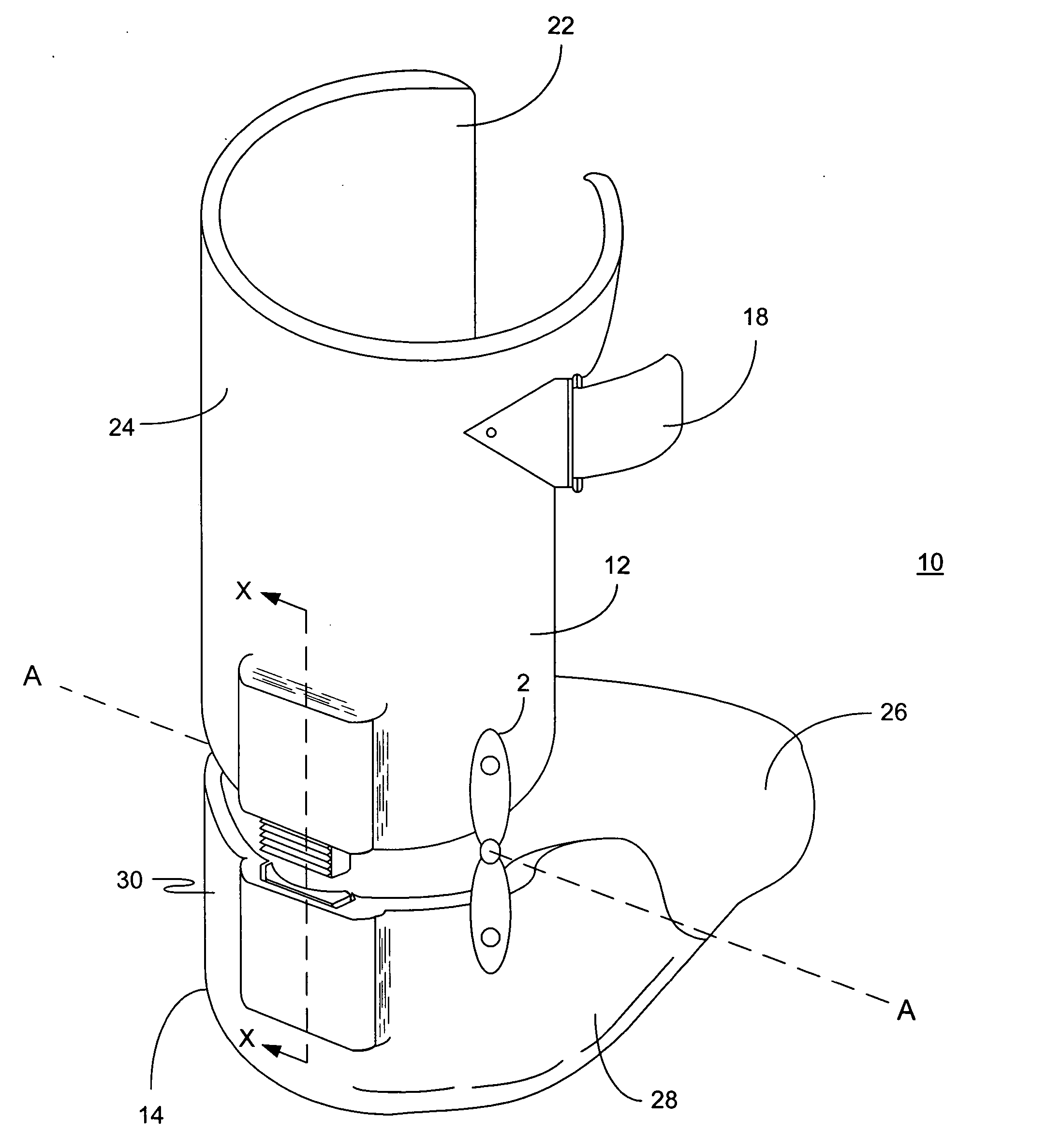
[0042] Preferred embodiments of the present invention are illustrated in FIGS. 1-12. Referring now to FIG. 1 an ankle-foot orthotic device for limiting the motion of a foot about an ankle joint is designated by numeral 10. The present description is directed primarily to an ankle-foot orthotic device; however, the method of fabrication and use of orthotic device 10 can readily be applied to other joints of the human anatomy.

[0043] Orthotic device 10 has an ankle section 12 and a foot section 14, hingedly linked to rotate about an axis A-A, by a pair of hinge mechanisms 2 and 4 (not shown). Hinge mechanisms 2 and 4 are fastened on opposite sides of orthotic device sections 12 and 14 using rivets, bolts, epoxy, or other fastening mechanism. Hinge mechanisms 2 and 4 may have moving parts like a door hinge or may be formed from a single piece of flexible material that will allow orthotic device sections 12 and 14 to pivot about axis A-A.

[0044] Ankle section 12 has an inner surface 22 ...


PUM


Abstract

An apparatus for quietly limiting motion at a limb joint having pivotally attached members for receiving the limbs of a joint and a dual-adjustable stop mechanism assembly operatively attached to the members for restricting movement at the joint. The dual-adjustable stop mechanism assembly includes at least one removably connected adjustable range of motion limiter.

Description

FIELD OF THE INVENTION [0001] The present invention relates to an ankle-foot orthosis with a dual-adjustable range of motion limiter for limiting the range of pivotal movement of the foot. Even more particularly, this invention relates to an orthotic range of motion limiter that allows for ease of manufacture of an ankle-foot orthosis and that allows the degree of plantar flexion and dorsiflexion of the foot to be adjusted and or fixed. BACKGROUND OF THE INVENTION [0002] Hinged orthopedic braces having an adjustable range of pivotal movement, as disclosed by U.S. Pat. Nos. 5,022,390 (1991) and 5,328,444 (1994), both to Whiteside, are known in the art. The braces disclosed therein have adjustable stopping mechanisms to limit the range in pivotal movement of two hinged members of the brace relative to each other. The stopping mechanisms taught by the above-mentioned patents disclose an adjustable stop mechanism attached to one member of the brace that is positioned to come into contac...

Claims


Application Information

Patent Timeline
IPC IPC(8): A61F5/01
CPCA61F5/0127
Inventor CURRIER, MARK R.
Owner CURRIER MARK R
Why Eureka
Try Eureka