Inductive devices and methods

a technology of inductive devices and inductance, applied in the direction of basic electric elements, inductance with magnetic cores, transformers/inductance details, etc., can solve the problems of inefficient use of cores, insufficient inductance tolerance, and insufficient inductance tolerance, etc., to achieve enhanced inductance tolerance and electrical performance, improved high-tolerance inductive devices, and reduced emi radiation

Active Publication Date: 2005-07-14
PULSE ELECTRONICS
View PDF8 Cites 59 Cited by
  • Summary
  • Abstract
  • Description
  • Claims
  • Application Information

AI Technical Summary

Benefits of technology

[0019] In a first aspect of the invention, an improved high-tolerance inductive device is disclosed. In one embodiment, the device comprises a unitary core base having a plurality of legs onto which one or more windings are disposed. A cap provides magnetic coupling for the windings of each leg. Use of a common core with a unitary base element provides significantly enhanced inductance tolerance and electrical performance (including reduced EMI radiation). Use of “one pass” windings on the device also mitigates radiated EMI and allows the core to be more magnetically efficient.

Problems solved by technology

Despite the foregoing broad variety of prior art inductor configurations, there is a distinct lack of a simplified and low-cost inductor configuration that provides a high degree of uniformity (tolerance).
This technique of distribution, however, also requires a high degree of uniformity or tolerance between the e.g., four devices; otherwise, additional components (such as a sense resistor) may be required, thereby adding additional cost and labor.
Also, some prior art inductive devices use “loop back” style (multi-turn) windings which introduce additional winding run length into the device, and also do not make the most efficient use of the core in terms of, inter alia, magnetic flux density distribution.

Method used


Image

  • Inductive devices and methods
  • Inductive devices and methods
  • Inductive devices and methods

Examples


Embodiment Construction

[0044] Reference is now made to the drawings wherein like numerals refer to like parts throughout.

[0045] As used herein, the term “magnetically permeable” refers to any number of materials commonly used for forming inductive cores or similar components, including without limitation various formulations made from ferrite.

[0046] As used herein, the term “winding” refers to any type of conductor, irrespective of shape, cross-section, or number of turns, which is adapted to carry electrical current.

Overview

[0047] The present invention provides, inter alia, improved inductive apparatus and methods for manufacturing, and installing the same.

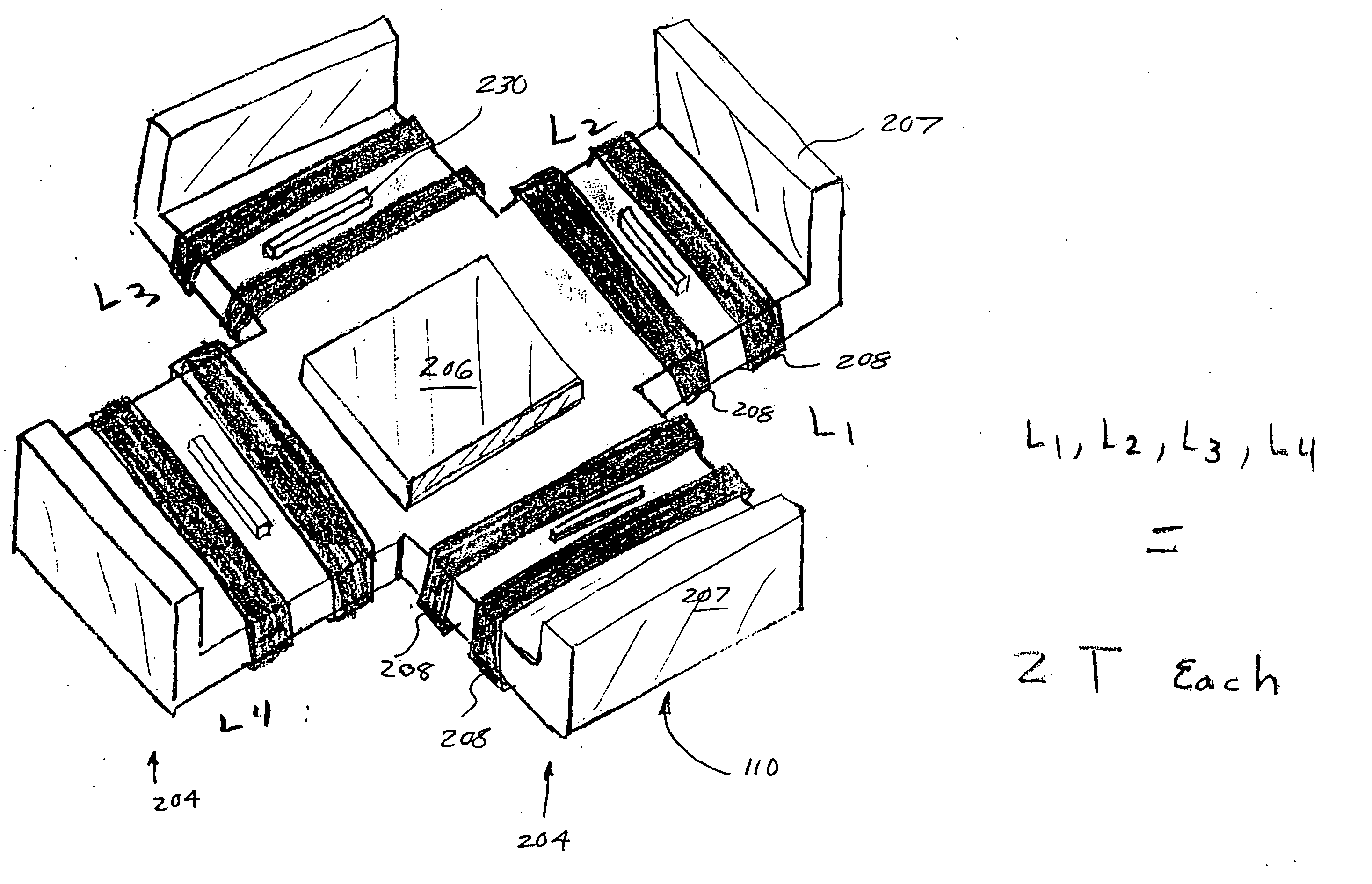
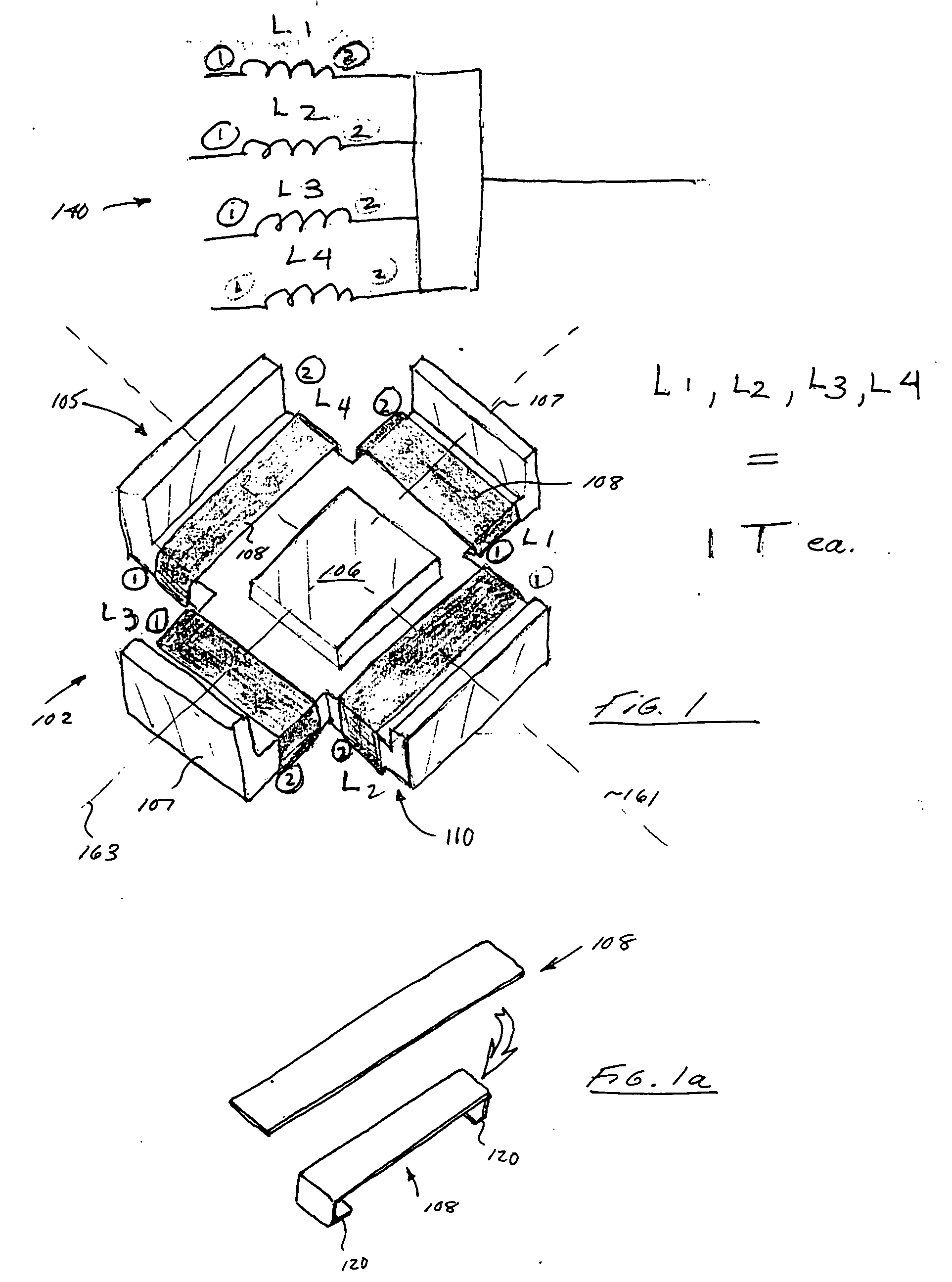
[0048] As noted above, a high degree of uniformity (tolerance) is often desirable for electronic circuit elements, especially were two or more such components are disposed in a common circuit. The present invention is advantageously adapted to overcome the disabilities of the prior art by (i) providing a common core configuration which eliminates...


PUM

PropertyMeasurementUnit
inductancesaaaaaaaaaa
magnetically permeableaaaaaaaaaa
magneticaaaaaaaaaa

Abstract

A low cost, low profile and high performance inductive device for use in, e.g., electronic circuits. In one exemplary embodiment, the device includes a four-legged ferrite core optimized for fitting with four or more windings, thereby providing four close-tolerance inductors. Optionally, the device is also self-leaded, thereby simplifying its installation and mating to a parent device (e.g., PCB). In another embodiment, multiple windings per leg are provided. In yet another embodiment, the device has only to opposed legs, thereby reducing footprint. Methods for manufacturing and utilizing the device are also disclosed.

Description

PRIORITY [0001] This application claims priority to U.S. Provisional Application Ser. No. 60 / 520,965 filed Nov. 17, 2003 of the same title, incorporated herein by reference in its entirety1. FIELD OF THE INVENTION [0002] The present invention relates generally to inductive circuit elements and more particularly to inductive devices having various desirable electrical and / or mechanical properties, and methods of operating and manufacturing the same. 2. DESCRIPTION OF RELATED TECHNOLOGY [0003] Myriad different configurations of inductors and inductive devices are known in the prior art. See, for example, U.S. Pat. No. 1,767,715 to Stoekle, U.S. Pat. No. 3,068,436 to Holmberg, et al, U.S. Pat. No. 3,585,553 to Muckelroy et al., U.S. Pat. No. 3,874,075 to Lohse, which represent various approaches to providing inductances within a circuit. [0004] Still other configurations are known. For example, U.S. Pat. No. 4,352,081 to Kijima issued Sep. 28, 1982 entitled “Compact trans core” disclos...

Claims


Application Information

Patent Timeline
Patent Type & Authority Applications(United States)
IPC IPC(8): H01F3/12H01F3/14H01F17/04H01F27/255
CPCH01F3/12H01F27/255H01F17/04H01F3/14
Inventor DADAFSHAR, MAJID
Owner PULSE ELECTRONICS
Why Eureka
Try Eureka