Electrically-operated dispenser

a dispenser and electric technology, applied in the direction of liquid transfer devices, operating means/releasing devices of valves, transportation and packaging, etc., can solve the problems of insufficient spacing between adjacent electrically operated liquid dispensers, poles, armatures and electromagnetic coils inside the dispensers that do not make efficient use of the open space inside the dispenser body, and intermittent flow discontinuities, etc., to achieve faster cycle rates, more magnetically efficient, and compact

Inactive Publication Date: 2005-10-20
NORDSON CORP
View PDF42 Cites 10 Cited by
  • Summary
  • Abstract
  • Description
  • Claims
  • Application Information

AI Technical Summary

Benefits of technology

[0009] The electrically-operated liquid dispenser of the invention is capable of operating at faster cycle rates and is more magnetically efficient than conventional electrically-operated liquid dispensers. In addition, the liquid dispenser is narrower than conventional electrically-operated liquid dispensers as the pole is flatter than conventional cylindrical poles. As a result, side-by-side arrangements of multiple dispensers of the invention is more compact. Moreover, individual sets of coil windings may be wrapped about one of the arms of the U-shaped pole and connected in par

Problems solved by technology

Hence, cyclic movement between the opened and closed positions causes intermittent flow discontinuities required to generate a pattern of liquid on a surface of the product or product packaging.
The conventional arrangement of the pole, armature and electromagnetic coil inside the liquid dispenser does not make efficient use of the open space available inside the dispenser's body.
As a result, the spacing between adjacent electrically-operated liquid dispensers cannot be sufficiently reduced, which is detrimental for some small footprint applications applying closely-spaced amounts of liquid on the surface of the produc

Method used


Image

  • Electrically-operated dispenser
  • Electrically-operated dispenser
  • Electrically-operated dispenser

Examples


Embodiment Construction

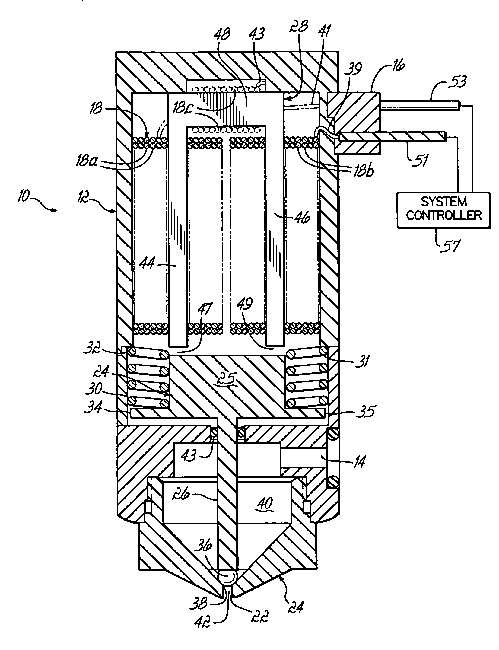
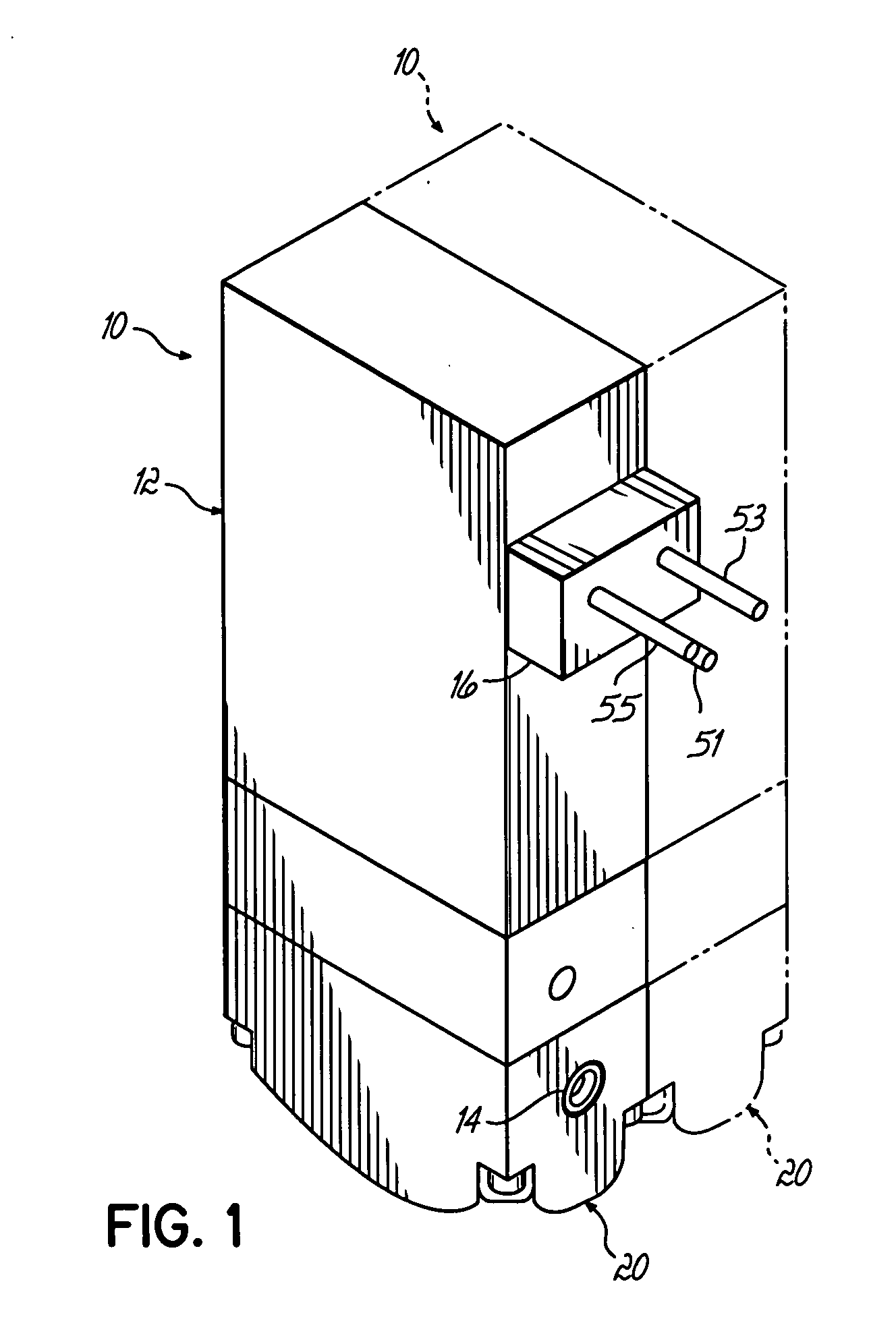
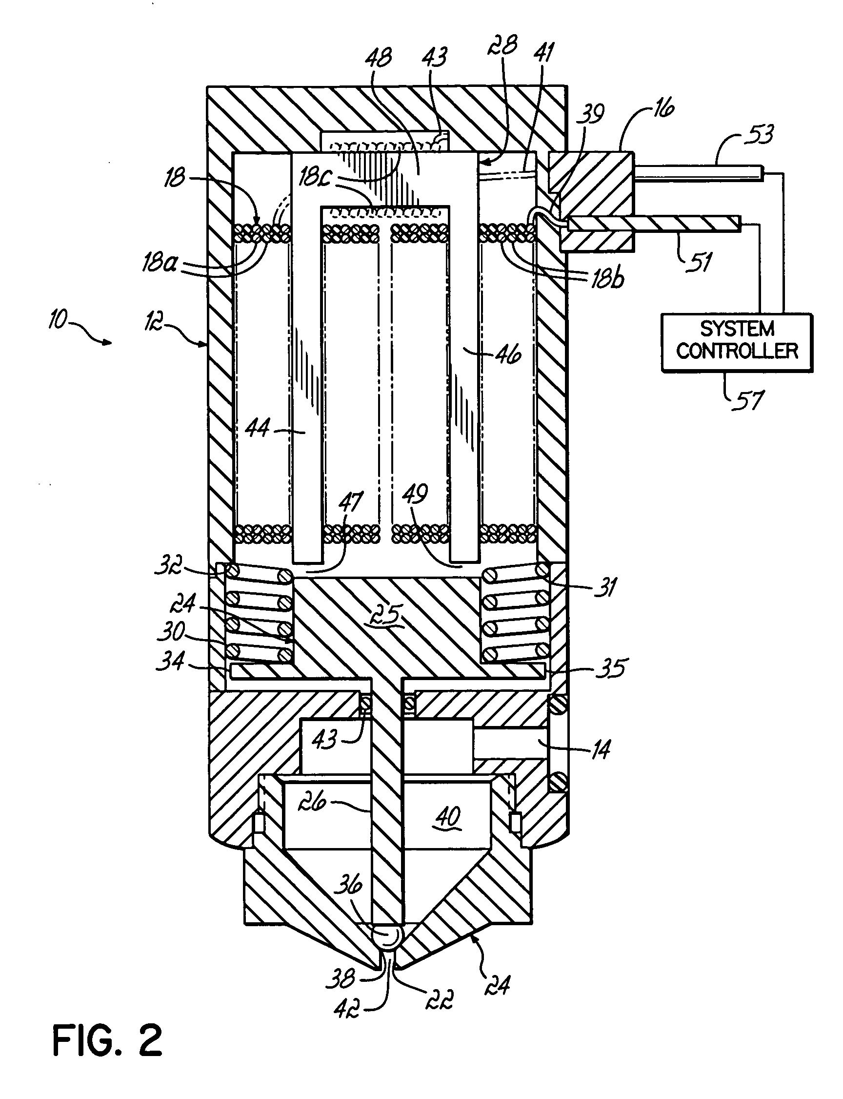
[0018] With reference to FIGS. 1-4, an electrically-operated gun or dispenser 10 for intermittently dispensing viscous liquids includes a module body 12 with a liquid inlet 14 for admitting liquid supplied under pressure from a liquid supply (not shown) and an electrical connector 16 capable of being coupled with a suitable complementary electrical connector with a system controller 57 (FIG. 2) for energizing a field-generating electromagnetic coil 18 housed inside the module body 12. Dispenser 10 may be used to dispense ambient temperature viscous liquids, including cold adhesives or glues, and heated viscous liquids, such as hot melt adhesives. The dispenser 10 is mounted in a dispensing machine or system (not shown) in a known manner for intermittently dispensing viscous liquid in discrete volumes, such as beads or dots, to provide an interrupted, non-continuous pattern on a moving substrate. As shown in FIG. 1, multiple dispensers 10 may be positioned side-by-side in a row withi...


PUM


Abstract

An electrically-operating liquid dispenser having an U-shaped pole. Windings of an electromagnetic coil are wound about the legs of the U-shaped pole and are energized selectively for moving an armature relative to the pole to open and close the dispenser. The U-shaped configuration of the pole conserves space within the dispenser and contributes to a narrow geometrical configuration for the dispenser, which allow more compact side-by-side arrangements of multiple dispensers. In certain embodiments, the windings may be divided into sets capable of being individually energized.

Description

FIELD OF THE INVENTION [0001] This invention relates generally to liquid dispensers and, more particularly, to an electrically-operated dispensers for dispensing viscous liquids. BACKGROUND OF THE INVENTION [0002] Liquid guns, modules and dispensers are routinely used to dispense viscous liquids, such as hot melt adhesives, sealants and other thermoplastic materials, in a variety of dispensing applications employed in the manufacture of products and in product packaging. The flow and discharge of liquid in conventional liquid dispensers is regulated by either a pneumatically-actuated valve assembly or an electrically-operated valve assembly. Generally, valve assemblies of liquid dispensers feature a valve element movable for selectively contacting a valve seat to provide distinct opened and closed conditions that permit and interrupt, respectively, the flow of liquid to a dispensing orifice. Hence, cyclic movement between the opened and closed positions causes intermittent flow disc...

Claims


Application Information

Patent Timeline
IPC IPC(8): B05C5/02B67D7/06
CPCB05C5/0225
Inventor SAIDMAN, LAURENCE B.
Owner NORDSON CORP
Why Eureka
Try Eureka