Fastener feed head

一种紧固件、供给头的技术,应用在薄料处理、扳手、金属加工设备等方向,达到快循环速率的效果

Active Publication Date: 2020-09-11
PENN AUTOMOTIVE INC
View PDF12 Cites 0 Cited by
  • Summary
  • Abstract
  • Description
  • Claims
  • Application Information

AI Technical Summary

Problems solved by technology

May not be able to run the installation head at the required cycles per minute because the installation equipment must wait for the fastener to be fed

Method used


Image

  • Fastener feed head
  • Fastener feed head
  • Fastener feed head

Examples


Embodiment Construction

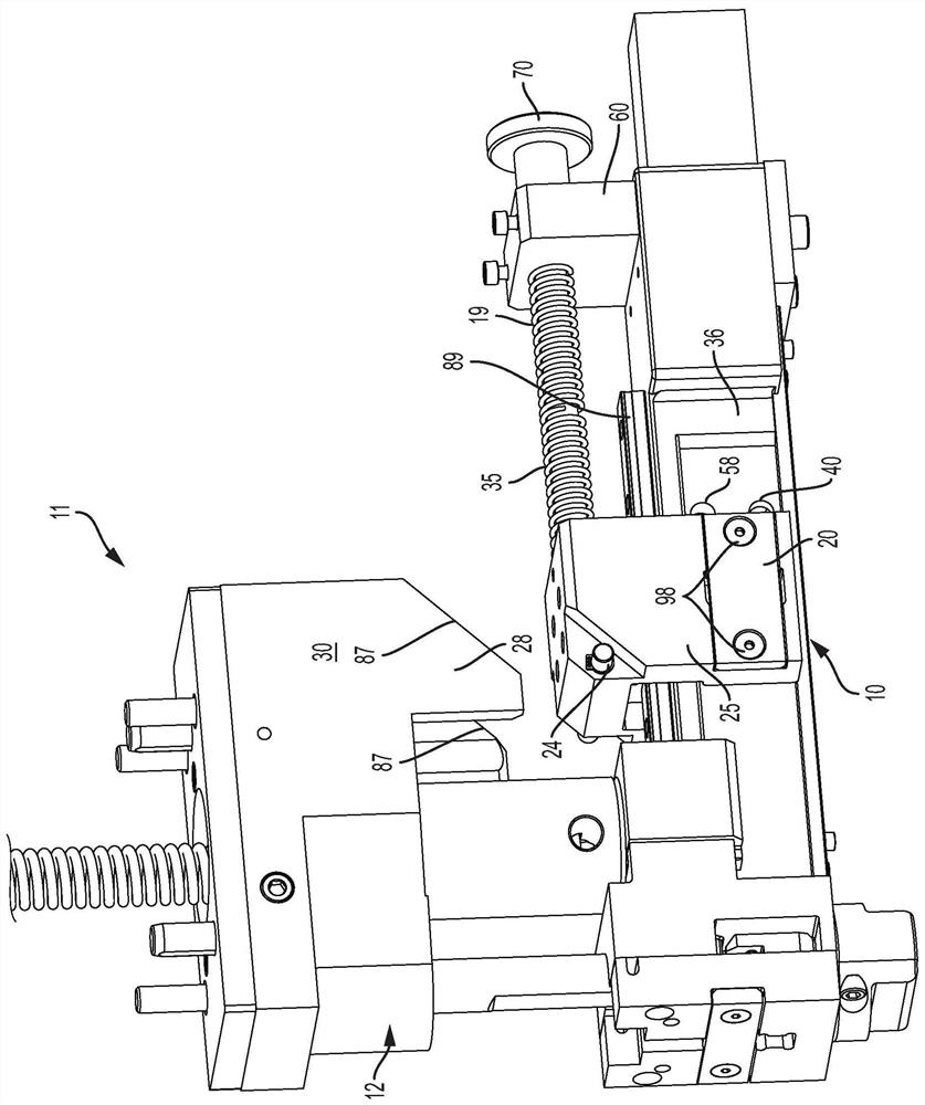
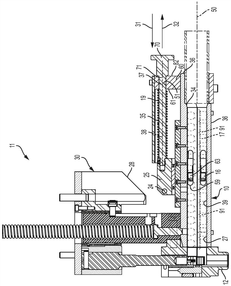
[0036] A fastener feeding head according to a preferred embodiment of the present invention is shown in the drawings and generally designated by the reference numeral 10 . In the embodiments illustrated herein and described below, the fastener feeding head 10 feeds fasteners 17 to the fastener installation head 12 of the fastener installation apparatus. refer to figure 1 , 2and 6 , the fastener feed head 10 includes a chute 36 having a feed passage 39 having an upstream region proximate to the chute inlet 34 , a downstream region proximate to the chute outlet 27 , and a feed axis 50 . The chute 36 may support and guide the fastener 17 from the chute inlet 34 to the chute outlet 27 coupled with the fastener installation head 12 . The fastener feeding head 10 may be used to feed any self-attaching fastener, including punched and set studs, bolts, ball studs, punched and set nuts, and other female fasteners of this type. exist figure 2 , Figure 8A , Figure 9 and Figur...


PUM


Abstract

A fastener feed head includes a chute having a feed passage along a feed axis to support and guide fasteners from a chute inlet to a chute outlet connected to a fastener installation head. A carriageis movably attached to the chute along a feed axis. Opposed pawls are pivotably attached to the carriage. The carriage reciprocates along the feed axis between a retracted position and a feed position. The carriage cyclically advances a predetermined number of fasteners from a queue of fasteners in an upstream zone into a queue of fasteners in a downstream zone by: retracting to the retracted position from the feed position; abutting the lead fastener in the upstream queue with the pawls; and, driving the lead fastener with the pawls until the carriage reaches the feed position.

Description

[0001] related application [0002] This application claims priority to U.S. Patent Application No. 15 / 849,638, filed December 20, 2017, and entitled "Fastener Feed Head." technical field [0003] The invention relates to an apparatus for feeding fasteners from a supply hopper to a mounting head of a fastener mounting device. Background technique [0004] Self-attaching fasteners can be attached to panels without welding. Examples of self-attaching fasteners include stamped and inserted studs, bolts, ball studs, stamped and inserted nuts, and other female fasteners of this type. A self-attaching fastener includes a fastener portion such as, for a male fastener, a threaded or unthreaded shank, and for a female fastener, a threaded or unthreaded hole. Self-piercing fasteners have a cylindrical portion that pierces an opening in a panel. Self-inserting fasteners deform and secure to metal directly surrounding a pre-formed opening in a panel. [0005] Self-attaching fastene...

Claims


Application Information

Patent Timeline
Patent Type & Authority Applications(China)
IPC IPC(8): B23P19/00B23P19/06B25B23/04B65H20/22B23Q7/10
CPCB23P19/001B23P19/062B23P19/006B23P19/004
Inventor 布莱恩·威金斯约翰·莱恩·泰勒罗伯·约翰·谢弗
Owner PENN AUTOMOTIVE INC
Why Eureka
Try Eureka