
a crystallizer

A crystallizer and crystallization chamber technology, applied in solution crystallization, evaporative separation crystallization, heat exchange cooling crystallization, etc., can solve the problems of low internal circulation power, impact, crystal dispersion, etc., to reduce flow resistance, simplify equipment structure, Reduce the effect of pipeline blockage

Active Publication Date: 2018-08-28
四川思特瑞锂业有限公司
View PDF12 Cites 0 Cited by
  • Summary
  • Abstract
  • Description
  • Claims
  • Application Information

AI Technical Summary

Problems solved by technology

[0003] 1. The internal circulation power in the crystallization equipment is small. Even if a propulsion type agitator is used in this document 1, it is difficult to generate a sufficient rate of liquid flow in the guide tube, which in turn affects the circulation rate of the entire crystallization equipment, resulting in Crystallization efficiency is low;
[0004] 2. The separation effect of the fine crystal particles mixed in the solution after heat exchange by the heat exchange tube is poor, causing most of the crystal particles to flow into the upper cylinder;
[0005] 3. The mechanism for driving and stirring is set at the bottom of the lower cylinder, which makes the crystallization discharge operation inconvenient;
[0006] 4. The lower end of the guide cylinder directly rushes to the bottom of the lower cylinder, which is easy to cause impact on the crystallization area at the bottom of the lower cylinder, causing the deposited crystals to be washed away, resulting in poor crystallization deposition effect, which in turn affects the discharged crystallization material quality

Method used


Image

  • a crystallizer
  • a crystallizer
  • a crystallizer

Examples


Embodiment Construction

[0028] The present invention will be further described below in conjunction with the accompanying drawings and specific embodiments.

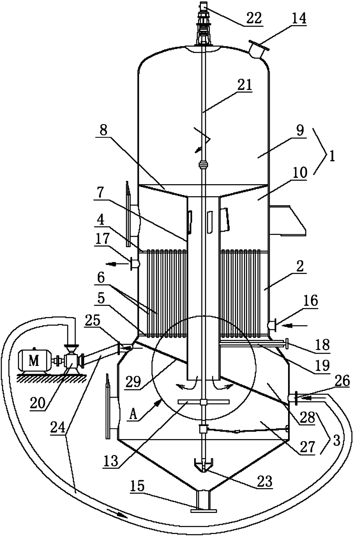
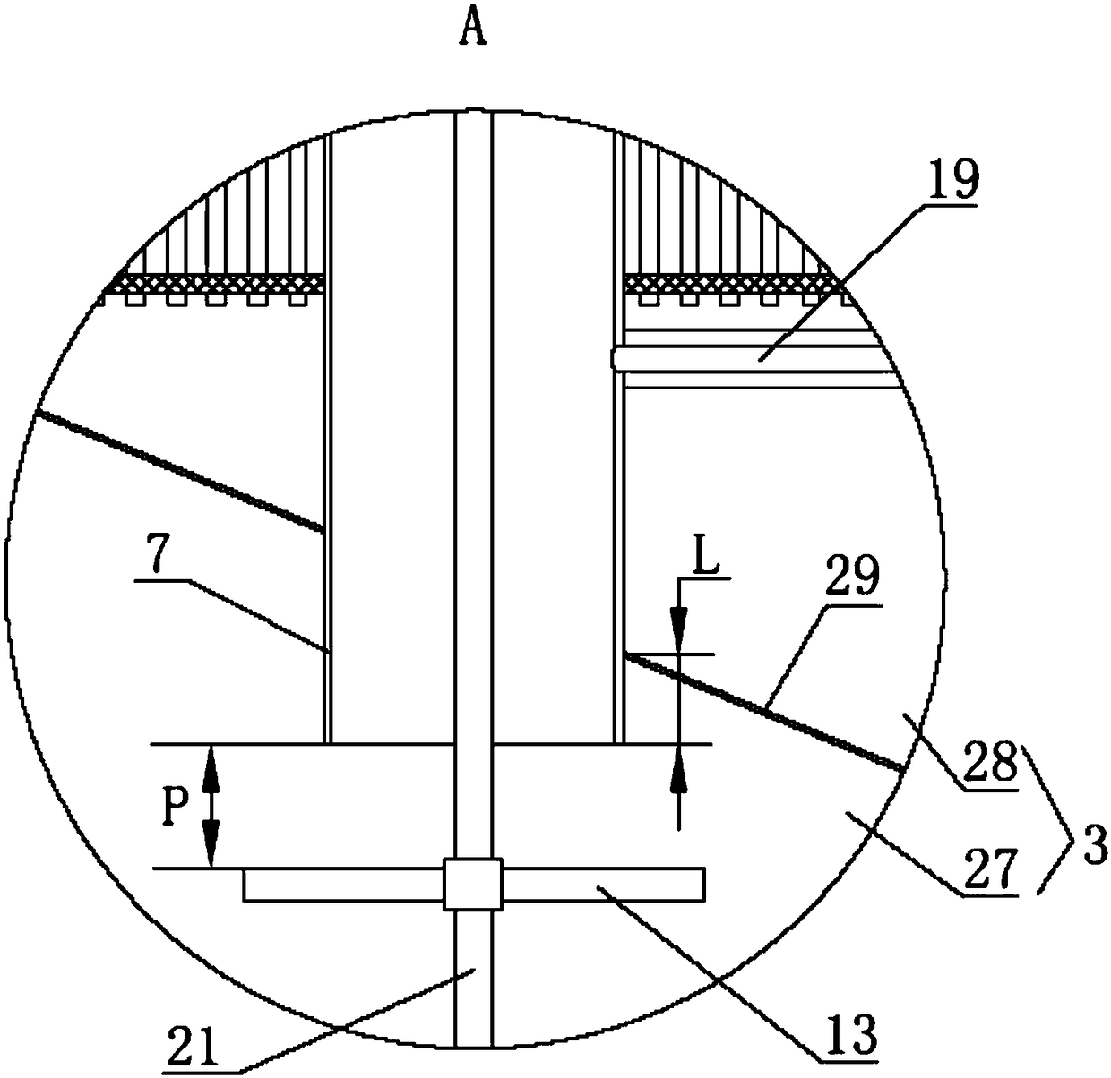
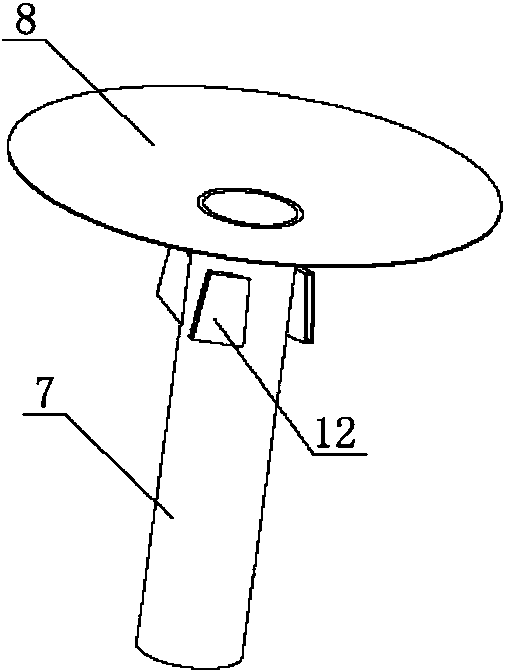
[0029] Such as figure 1 As shown in , a crystallizer according to the present invention includes an upper chamber 1, a heat exchange chamber 2 and a crystallization chamber 3 connected sequentially from top to bottom; between the upper chamber 1 and the heat exchange chamber 2 is provided The upper tube sheet 4 is provided with the lower tube sheet 5 between the crystallization chamber 3 and the heat exchange chamber 2; the heat exchange tube 6 is arranged in the heat exchange chamber 2, and the lower end of the heat exchange tube 6 passes through the lower tube sheet 5 It communicates with the crystallization chamber 3, and the upper end of the heat exchange tube 6 passes through the upper tube plate 4 and communicates with the upper chamber 1; it also includes a guide tube 7, which passes through the heat exchange chamber 2, and the guide tub...


PUM


Abstract

The invention discloses a crystallizer, belongs to the field of crystallizing equipment, and provides a crystallizer, which aims at effectively improving liquid circulation rate in the crystallizing equipment and further improving crystallizing efficiency. The crystallizer comprises an upper chamber, a heat exchange cavity, a crystallizing chamber, a flow guide pipe and an oblique plate, wherein the upper cavity, the heat exchange chamber and the crystallizing chamber are sequentially connected from top to bottom; the flow guide pipe penetrates through the heat exchange chamber; the oblique plate is used for separating the crystallizing chamber into an upper circulation cavity and a lower crystallizing cavity; the lowest part of the circulation cavity is provided with a circulation liquid inlet which is communicated with the circulation cavity, and the highest part of the crystallizing cavity is provided with a circulation liquid outlet which is communicated with the crystallizing cavity; the circulation liquid inlet and the circulation liquid outlet are communicated through a circulation pipeline, and a circulation pump is arranged on the circulation pipeline. The crystallizer has the advantages that forced circulation power is provided for the whole crystallizer through the circulation pump, thus the higher liquid circulation rate and the larger circulation flow rate in the crystallizer are guaranteed, and the crystallizing efficiency of the whole crystallizer is guaranteed.

Description

technical field [0001] The invention relates to the field of crystallization equipment, in particular to a crystallizer capable of continuous crystallization. Background technique [0002] Crystallizer is a kind of equipment used for product crystallization operation, generally divided into two types: evaporative crystallizer and cooling crystallizer. A patent document with publication number CN202155069U (hereinafter referred to as document 1) discloses an "internal circulation evaporative crystallizer" (the entirety of which is hereby cited in this application). The crystallizer disclosed in this document 1, compared with the traditional external circulation crystallizer, can simplify the equipment structure, and can greatly reduce the power consumption of equipment operation, and can effectively solve the problem of using traditional external circulation crystallization equipment. Sometimes it is easy to cause the problem that the whole crystallization equipment cannot b...

Claims


Application Information

Patent Timeline
Patent Type & Authority Patents(China)
IPC IPC(8): B01D9/02
CPCB01D9/0013B01D9/0031
Inventor 陈思伟
Owner 四川思特瑞锂业有限公司
Learn More