
Horizontal forging press for massive forming

a forging press and horizontal technology, applied in forging presses, forging/hammering/pressing machines, forging/pressing/hammering apparatuses, etc., can solve the problems of comparatively long pressure dwell time, high maintenance requirements for hydraulics, and relatively low cycle speed

Active Publication Date: 2015-03-26
SCHULER PRESSEN GMBH & CO KG
View PDF1 Cites 0 Cited by
  • Summary
  • Abstract
  • Description
  • Claims
  • Application Information

AI Technical Summary

Benefits of technology

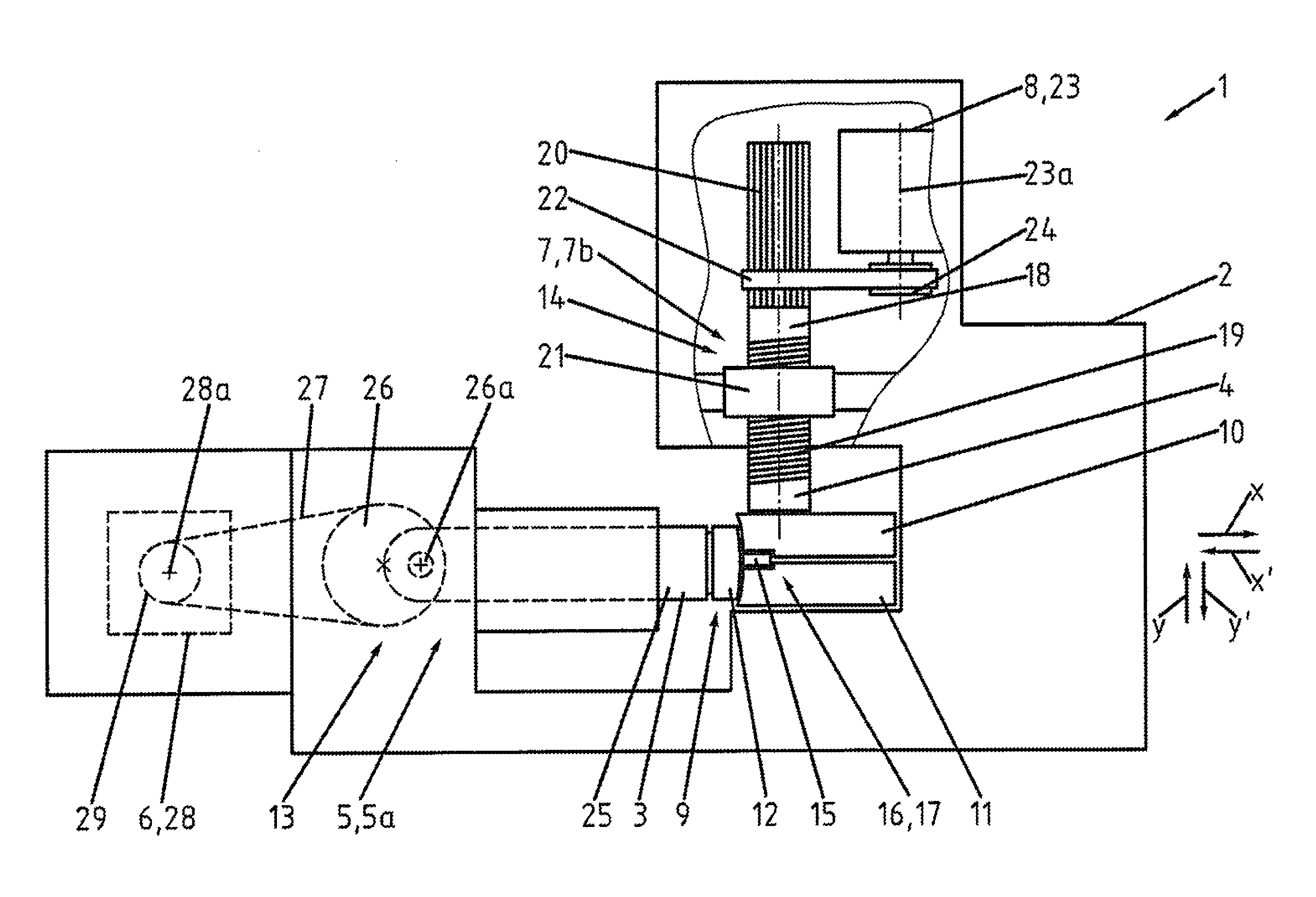
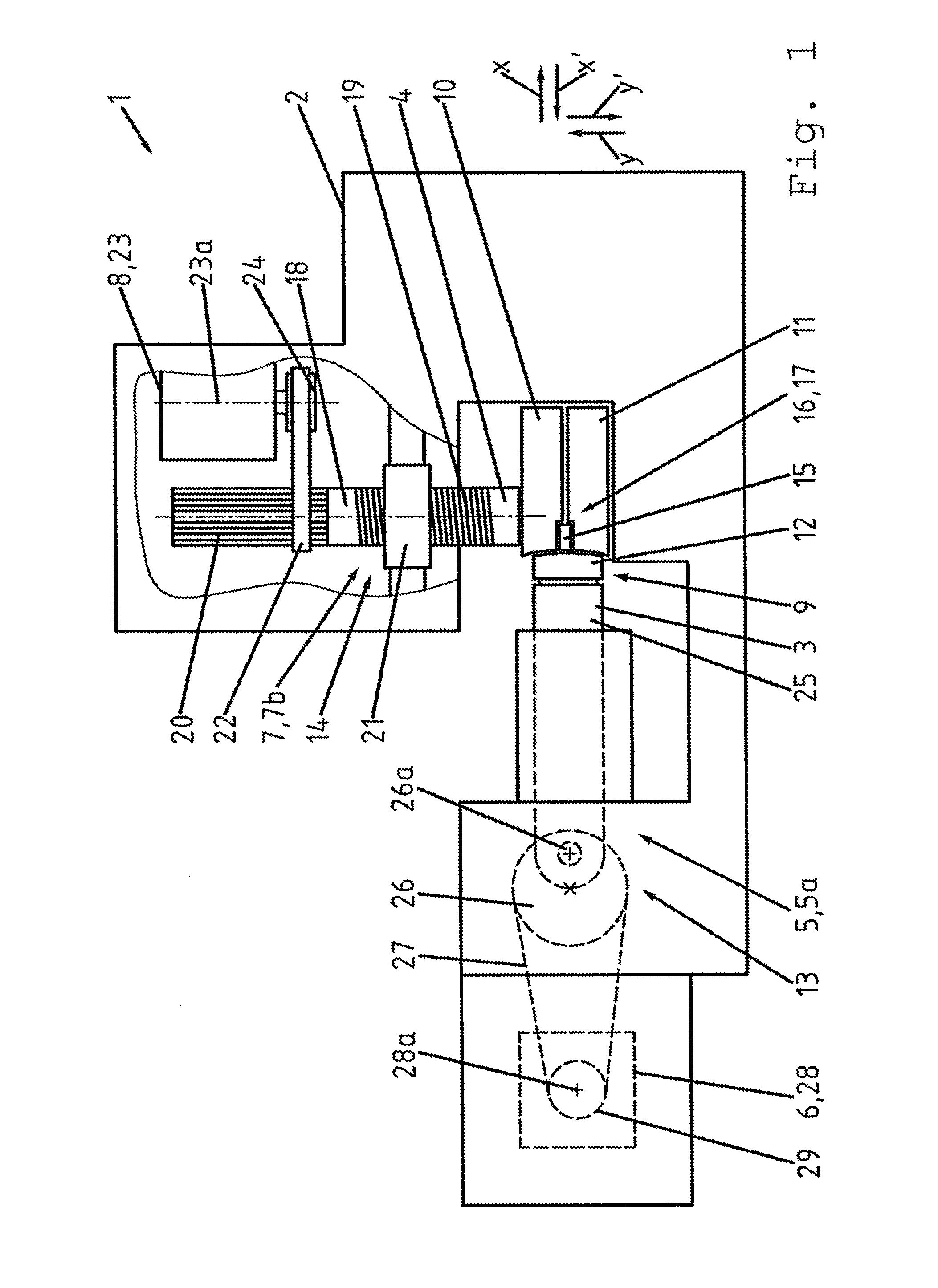
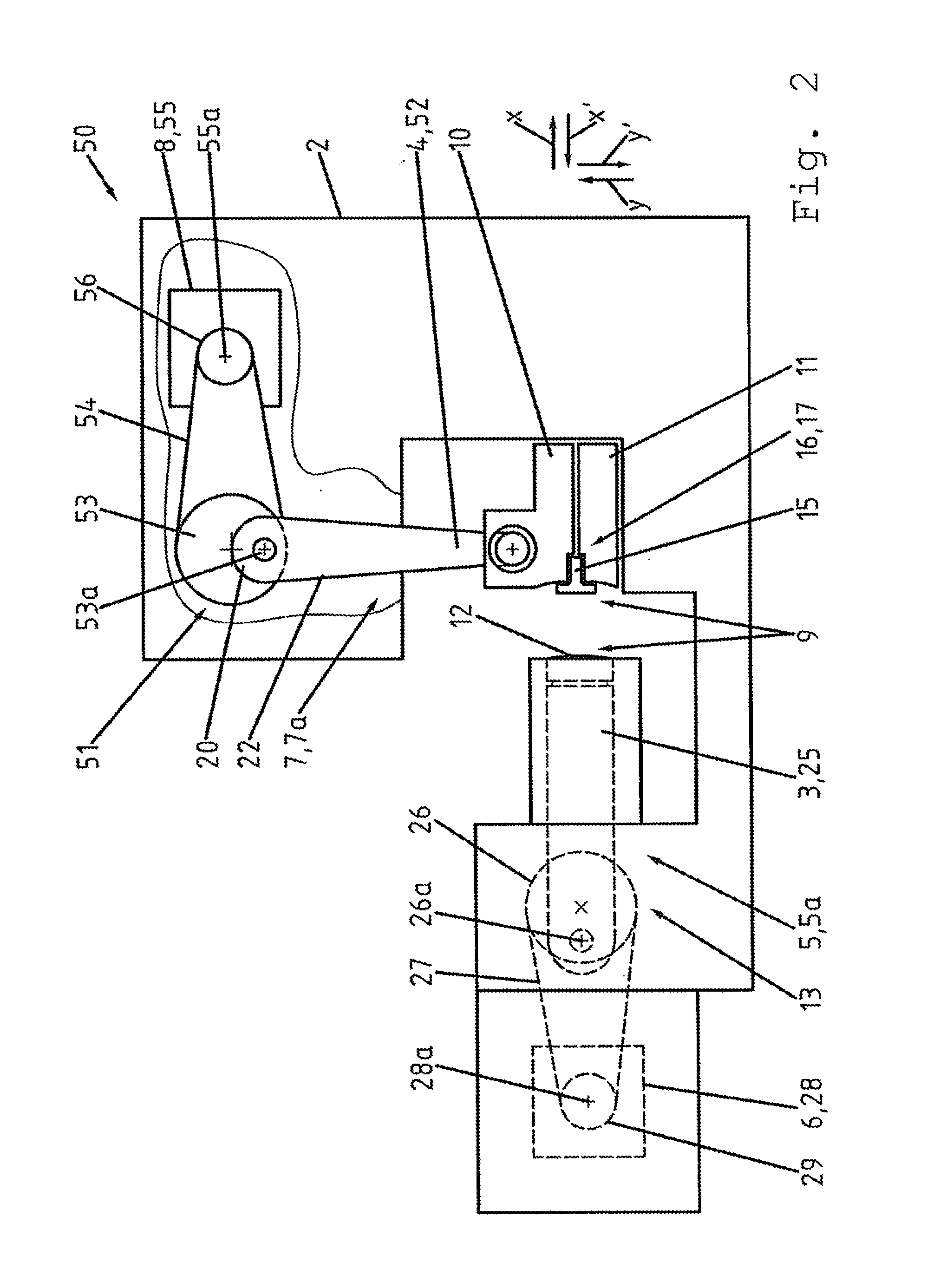
The invention is a horizontal forging press that has a low maintenance requirement, is suitable for high cycle speeds, and has short pressure dwell times. The press has a first force transmission device that controls the movement of the forging ram and can be configured as a stroke-controlled force transmission device or an energy-controlled force transmission device. The press also has a multipart forging tool with two movable parts that can be optimally met through the use of the appropriate force transmission device. The first force transmission device can be a crank mechanism, a toggle mechanism, or an eccentric mechanism, all of which ensure a short pressure detection time for forging.

Problems solved by technology

Disadvantages of a machine of this type are the high maintenance requirement for the hydraulics, the relatively low cycle speed and the comparatively long pressure dwell times.

Method used


Image

  • Horizontal forging press for massive forming
  • Horizontal forging press for massive forming
  • Horizontal forging press for massive forming

Examples


Embodiment Construction

[0021]In FIG. 1, a schematic side view of a first construction variant of a horizontal forging press 1 is shown. The horizontal forging press 1 comprises a machine frame 2, a forging ram 3 for executing a horizontal forging motion or working motion in an arrow direction x, a clamping ram 4 for executing a vertical clamping motion or working motion in an arrow direction y′, a first force transmission device 5 for moving the forging ram 3, which device is driven by a first drive 6, a second force transmission device 7 for moving the clamping ram 4, which device is driven by a second drive 8, and a multipart forging tool 9. The multipart forging tool 9 is configured as a three-part forging tool 9 having a first, upper clamping jaw 10, a second, lower clamping jaw 11, and a forging jaw 12. The first force transmission device 5 for the forging ram 3 is here configured as a stroke-controlled force transmission device 5a and formed by a crank mechanism 13. The second force transmission dev...


PUM

PropertyMeasurementUnit
Angleaaaaaaaaaa

Abstract

The invention relates to a horizontal forging press for massive forming, which comprises a machine frame, a forging ram, a clamping ram, at least a first force transmission device, at least a second force transmission device, and a multipart forging tool, wherein each force transmission device comprises at least one drive. The first force transmission device of the forging ram is here configured as a stroke-controlled force transmission device, and the second force transmission device of the clamping ram is here configured as a stroke-controlled force transmission device or as an energy-controlled force transmission device.

Description

CROSS REFERENCE TO RELATED APPLICATION[0001]This application is a continuation of International Application No. PCT / EP2013 / 001163 filed Apr. 19, 2013, which designated the United States, and claims the benefit under 35 USC §119(a)-(d) of German Application No. 10 2012 008 180.4 filed Apr. 26, 2012, the entireties of which are incorporated herein by reference.FIELD OF THE INVENTION[0002]The invention relates to a horizontal forging press for massive forming.BACKGROUND OF THE INVENTION[0003]From the corporate publication “Upgrade—Journal for customers, partners and employees—12th. year, issue no. 23, Dec. 2009,” a hydraulic horizontal forging machine is known, which machine comprises a machine frame, a forging ram for executing a horizontal forging motion, a clamping ram for executing a clamping motion oriented rotated through 90° relative to the forging motion, at least a first force transmission device for executing the forging motion of the forging ram, at least a second force tran...

Claims


Application Information

Patent Timeline
IPC IPC(8): B21J9/18B21J13/04B21J9/02
CPCB21J9/18B21J13/04B21J9/02B21J9/022B30B1/26B30B15/02B30B15/282
Inventor BIEG, MARKUSVOGEL, GERHARD
Owner SCHULER PRESSEN GMBH & CO KG
Learn More