Method of fabricating a magnetic flux channel for a transverse wound motor

a transverse wound and magnetic flux technology, applied in the direction of magnetic bodies, manufacturing stator/rotor bodies, magnetic circuit shapes/forms/construction, etc., can solve the problems of only blocking one plane of eddy current, reducing the maximum amount of torque produced, and adding silicon actually worsening the magnetic conductivity. , to achieve the effect of reducing eddy current, increasing overall efficiency, and reducing eddy curren

Inactive Publication Date: 2010-01-05
RITTENHOUSE NORMAN
View PDF19 Cites 31 Cited by
  • Summary
  • Abstract
  • Description
  • Claims
  • Application Information

AI Technical Summary

Benefits of technology

[0022]A sixth objective of the invention is to provide methods, apparatus and systems for a high efficiency direct drive high torque motor constructed using Parallel Pole Molded Magnetic Flux Channels, which increases the overall efficiency by greatly reducing eddy currents in all planes.
[0023]A seventh objective of the invention is to provide methods, apparatus and systems for a high efficiency direct drive high torque motor using Parallel Pole Molded Magnetic Flux Channels to reduce cost, and make possible more magnetically efficient shapes which results in higher overall efficiency.
[0024]An eighth objective of the invention is to provide methods, apparatus and systems for a high efficiency direct drive high torque motor that uses radial flux construction, but the preferred embodiment is Transverse Flux construction. In Transverse Flux construction, one large single winding powers each phase. This reduces the complexity and losses typically encountered with multiple salient type windings.
[0025]A ninth objective of the invention is to provide methods, apparatus and systems for a high efficiency direct drive high torque motor with fewer turns, and higher amperages. With fewer turns, the inductance is less, and with larger copper or aluminum windings the electrical resistance is less also. Since the inductance and resistance can be much less, both the inductive losses and the resistive losses are greatly reduced. The result is higher efficiency and also a much greater usable speed range.
[0026]A tenth objective of the invention is to provide methods, apparatus and systems for a Transverse Flux motor having a simplified construction and lowered costs, and at the same time increases electrical efficiency to a higher level than the prior art.

Problems solved by technology

However, even with thinner laminations, the eddy currents are only blocked in one plane.
Although the silicon reduces some remaining eddy current losses (by reducing the current conductivity), the addition of silicon actually worsens the magnetic conductivity.
This reduction of magnetic strength reduces the maximum amount of torque produced, and also reduces electrical efficiency.
The close-coupled proximity results in “Armature Effect” which reduces efficiency at higher speeds.
At higher speeds, the inductive and reactive losses limit top speed and efficiency at high speed.
However, it does not involve Transverse Flux and does not use molded material for the stator.
Transverse wound electric motors were first patented in 1895, and have evolved more slowly than conventional salient wound motors, due partly to material limitations.
While nearly all salient wound motors use laminated magnetic structures to reduce eddy current losses and accompanied heating, this technique is not optimal to transverse wound motors.
In salient wound motors, this is commonly done, but most transverse wound stators waste about half of the potentially useful magnetic flux.
Prior art transverse flux motors have historically been too costly to construct, and have rarely been used.

Method used


Image

  • Method of fabricating a magnetic flux channel for a transverse wound motor
  • Method of fabricating a magnetic flux channel for a transverse wound motor
  • Method of fabricating a magnetic flux channel for a transverse wound motor

Examples


Embodiment Construction

[0052]Before explaining the disclosed embodiments of the present invention in detail it is to be understood that the invention is not limited in its application to the details of the particular arrangements shown since the invention is capable of other embodiments. Also, the terminology used herein is for the purpose of description and not of limitation.

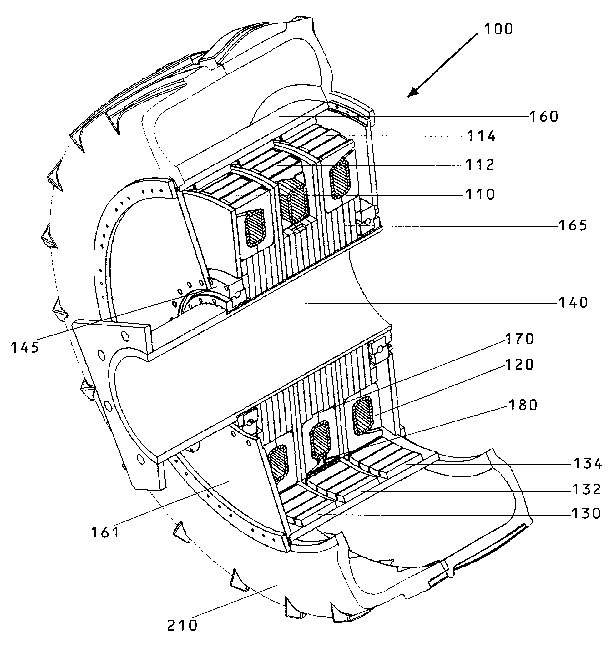
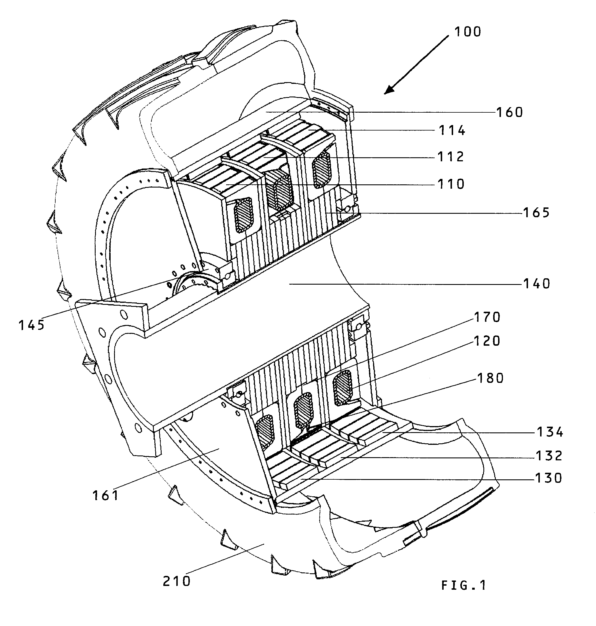
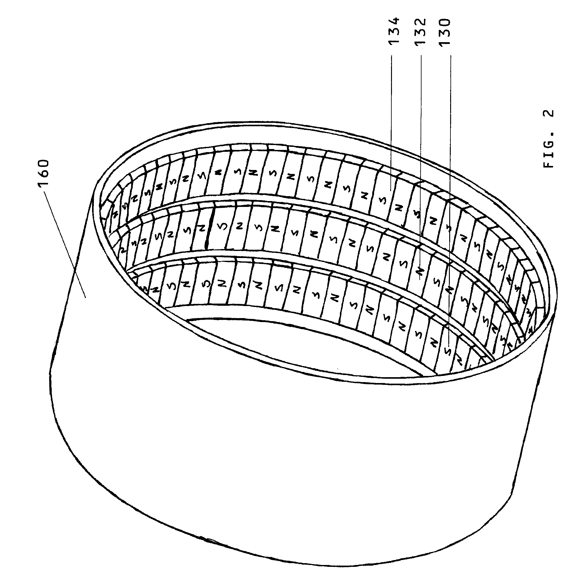
[0053]The following is a list of the reference numbers used in the drawings and the detailed specification to identify components:

[0054]

100motor106bundle of insulated wires104mold and stator housing107bundle of insulated iron tape108matrix of powder or binder162mounting shaft hole110pole pieces, phase “A”165hub112pole pieces, phase “B”170locating key114pole pieces, phase “C”172north parallel pole piece120transverse wire winding174south parallel pole piece130row of magnets, Phase “A”175hollow core132row of magnets, Phase “B”177air gap134row of magnets, Phase “C”200wheel motor140mounting shaft210tire145bearing220location ridge150Magnet...


PUM

PropertyMeasurementUnit
diameteraaaaaaaaaa
sizeaaaaaaaaaa
sizeaaaaaaaaaa

Abstract

Methods of fabricating a magnetic flux channel for a transverse wound electric motor by forming a ring of plural adjacent molded magnetic flux channel pole pieces and a second ring of opposite pole pieces. The two rings are mated such that each pole piece mates with an opposite pole piece to form magnetic flux channels and a c-shaped recess forms a winding channel for a transverse phase winding. After mating, the rings are bonded together to form a stator assembly of the transversely wound electric motor. The two rings may be approximately identical, or the two rings may be different as long as they mate to form the plural molded magnetic flux channels and the transverse phase winding channel. The molds may be designed to form the outer surface of a stator assembly. Molds of adjacent phases may be combined back-to-back to reduce part count and increase mechanical strength.

Description

[0001]This application is a continuation-in-part of U.S. patent application Ser. No. 12 / 015,718 filed on Jan. 17, 2008, now U.S. Pat. No. 7,579,742 issued on Aug. 25, 2009.FIELD OF THE INVENTION[0002]This invention relates to transverse flux motors and, in particular, to methods, apparatus and systems for arranging and casting Molded Magnetic Flux Channels within a permanent female mold which houses and supports the stator assembly of a high efficiency direct drive high torque motor utilizing parallel pole molded magnetic flux channels with transverse flux stator windings, and separate stators for each phase.BACKGROUND AND PRIOR ART[0003]Approximately 93% of motors constructed use iron cores, or variations thereof, to concentrate magnetic flux and boost torque. “Coreless” motors are suited for very high RPM's with low torque and iron core motors usually utilize insulated steel laminations in their stators, which reduce heat losses from eddy currents. However, even with thinner lamin...

Claims


Application Information

Patent Timeline
Patent Type & Authority Patents(United States)
IPC IPC(8): H02K15/00
CPCH02K1/145H02K1/2786Y10T29/49009Y10T29/49073Y10T29/49012Y10T29/49071Y10T29/49069Y10T29/49075B33Y80/00H02K1/2791
Inventor RITTENHOUSE, NORMAN
Owner RITTENHOUSE NORMAN
Why Eureka
Try Eureka