
Ergonomic watch case, time display and setting crown

a technology of time display and ergonomics, applied in the field of wrist watches, can solve the problems of less than ergonomically optimal watch display geometry in the above-discussed watch display

Inactive Publication Date: 2005-07-14
EQUITIME
View PDF10 Cites 4 Cited by
  • Summary
  • Abstract
  • Description
  • Claims
  • Application Information

AI Technical Summary

Benefits of technology

[0009] The present invention provides effective remedies for the above-discussed drawbacks by introducing new geometries for wrist watch cases and time displays, plus a relocated optimal position for a setting crown enabled by such geometries. In particular, the invention is based on forming watch cases generally in the shape of an obtuse triangle and offsetting the horizontal axis or bisector of the time display in the watch face, by a controlled extent, from perpendicular to the vertical bisector of the case, display and watch strap. As a result, the angle between the horizontal bisector of the time display and the viewer's line of sight is automatically reduced when the arm is raised in the usual position to read the time.
[0010] In addition, the triangular shape of the watch case enables locating a setting crown in an apical position at an upper apex of the case, which permits minimizing the axial thickness of the crown knob due to more free space provided by such geometry to the user's fingers, especially when the knob is in a rest position within or adjacent such apex. These advantages also assist stylists to design new and more imaginative watch appearances based upon the innovative geometries provided by the present invention.
[0011] Still another innovation is use of a three-note chime melody and icon which provide a more pleasing and acceptable wake up call or other time that the user wishes to hear.

Problems solved by technology

The geometries inherent in the above-discussed watch displays are less than ergonomically optimal, due to the difference in angles between the horizontal axis of the time displays and the viewer's arm position and line of sight when reading the time.

Method used


Image

  • Ergonomic watch case, time display and setting crown
  • Ergonomic watch case, time display and setting crown

Examples


Embodiment Construction

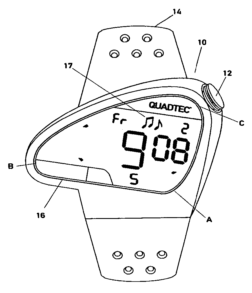
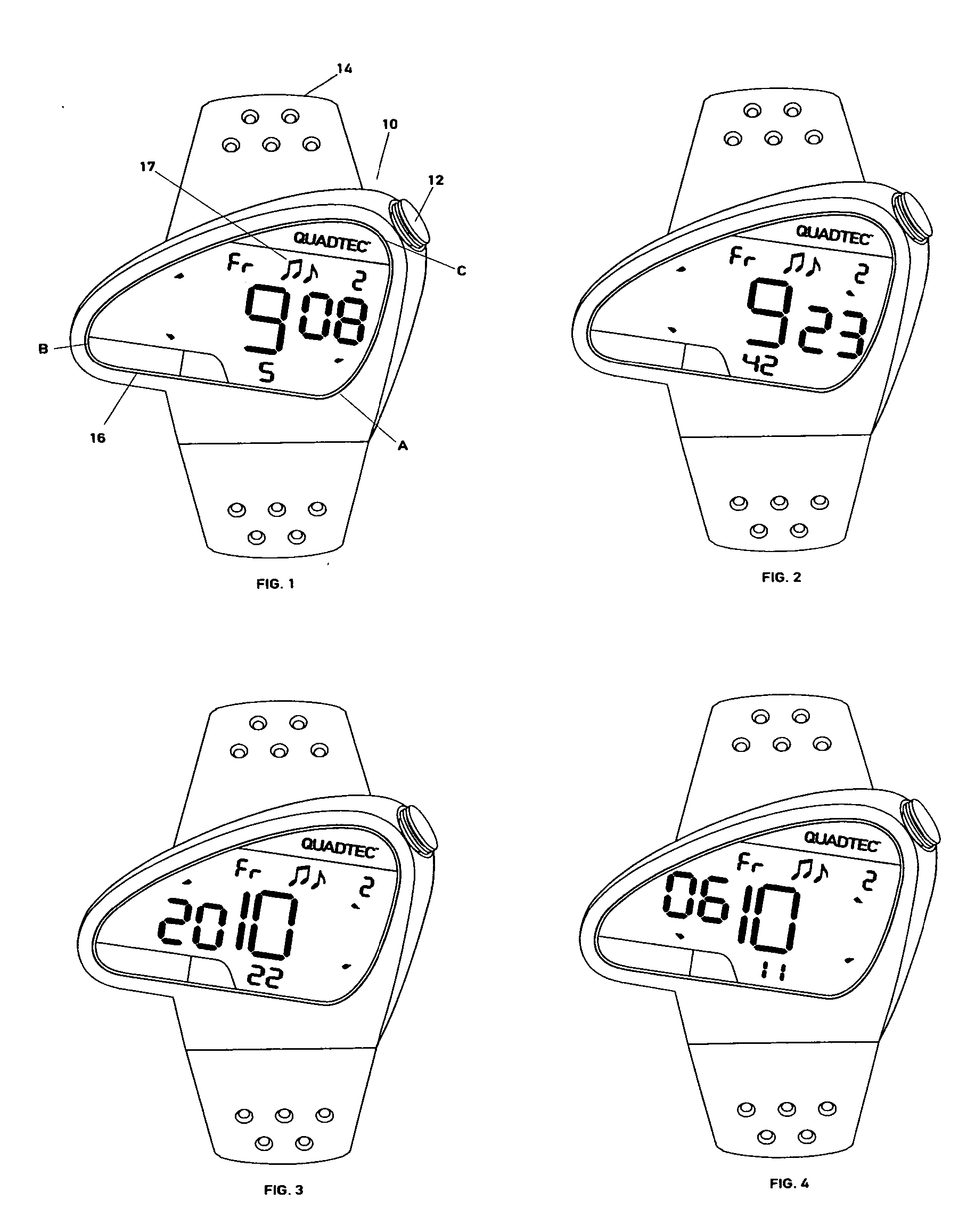
[0017] Referring to FIG. 1, a watch case 10 is there illustrated formed in a generally obtuse triangular shape, with the obtuse angle at apex A and acute angles at apices B and C. In this specific embodiment, such angles are approximately 100° for A, 30° for B and 50° for C. A single setting crown 12 is located adjacent case 10 at apex C. The case 10 is connected to watch strap 14.

[0018] A horizontal bisector through the display of hour 9 and 8 minutes is generally parallel to the bottom 16 of the inner perimeter of case 10 surrounding the time display field within the watch face. This bisector divides the time display field within the case generally in half. The watch strap 14 also has a vertical bisector that divides it generally in half.

[0019] The bottom perimeter 16 and the horizontal bisector of the time display are displaced clockwise by approximately 7° out of perpendicularity with the vertical bisector of the watch strap. As a result, when a viewer's arm is raised to an an...


PUM


Abstract

An ergonomic watch case, time display and setting crown are provided, with the case shaped generally in the form of an obtuse triangle and attached to a watch strap. A horizontal bisector through the case and time display is offset by a predetermined angle out of perpendicularity with a vertical bisector through the watch strap to improve alignment with a viewer's line of sight when reading the time. An apical setting crown is located at the apex of one of the two acute angles of the case to improve rotation of a crown knob in either direction with minimal resistance or obstruction from the watch case. A chime melody and icon are provided to sound a pleasing wake up call or other time set to be heard.

Description

BACKGROUND OF THE INVENTION [0001] 1. Field of the Invention [0002] This invention relates to wrist watches and, more particularly, to the introduction of ergonomic elements in watch cases, time displays and setting crowns which provide advantages in the viewing of time and the operation of watches containing such elements. [0003] 2. Description of the Prior Art [0004] Conventional digital wrist watches generally display time by a horizontal array of hours, minutes and seconds reading the watch face from left to right in that order. This array is normally disposed perpendicularly to the vertical bisector of the watch face. [0005] Other time displays characterized as quadribalanced, balanced, enhanced quadribalanced, and unidirectional segmented are disclosed in several patents, for example, U.S. Pat. No. 4,271,497, U.S. Pat. No. 4,627,737, U.S. Pat. No. 6,215,736 and U.S. Pat. No. 6,584,041, the disclosures of which are incorporated herein by reference. In these displays, during the...

Claims


Application Information

Patent Timeline
IPC IPC(8): A44C5/00G04G17/00
CPCG04G17/00
Inventor TERZIAN, BERJ A.BRODMANN, ROBERT ALFRED
Owner EQUITIME
Learn More