Bearing assembly with wear-resistant bearing surfaces

a bearing surface and bearing technology, applied in the direction of bearings, shafts and bearings, rotary bearings, etc., can solve the problems of friction between the bearing surface of the bearing and the outer surface of the shaft, accelerate surface wear, and wear between the two surfaces, so as to improve the wear resistance ability, reduce the wear thereon, and the effect of the same abrasive resistan

Inactive Publication Date: 2005-07-14
HON HAI PRECISION IND CO LTD
View PDF3 Cites 14 Cited by
  • Summary
  • Abstract
  • Description
  • Claims
  • Application Information

AI Technical Summary

Benefits of technology

[0005] The present invention is directed to a bearing assembly which can provide an improved wear-resistant ability.
[0006] A bearing assembly having features of the present invention comprises a tube axially defining an inner hole, a radial bearing fixed in the inner hole of the tube and an inner bearing surface concentric with the inner hole, and a shaft pivotably received in the inner hole. The shaft comprises a contact portion circumferentially formed at an outer periphery of the shaft confronting with the inner bearing surface of the bearing. The contact portion comprises an outer bearing surface being configured to have a substantially same abrasive resistance with the bearing surface to reduce wear thereon.

Problems solved by technology

This will inevitably cause wear on the outer surface of the shaft and the bearing surface of the bearing.
Once the wear occurs, wear particles are produced between the two surfaces.
The scratch will accelerate the surface wear.
As the wear becomes worse, the rotation of the shaft becomes unstable, the rotational precision decreases quickly, disgusting noise will be generated, and the lifespan of the electronic equipments will thus be shortened.

Method used


Image

  • Bearing assembly with wear-resistant bearing surfaces
  • Bearing assembly with wear-resistant bearing surfaces
  • Bearing assembly with wear-resistant bearing surfaces

Examples


Embodiment Construction

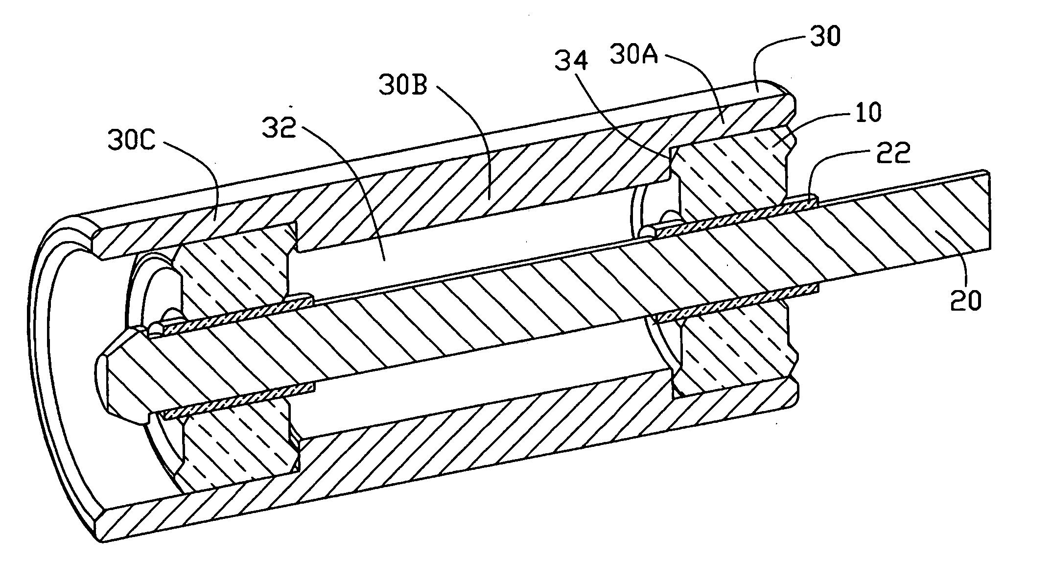
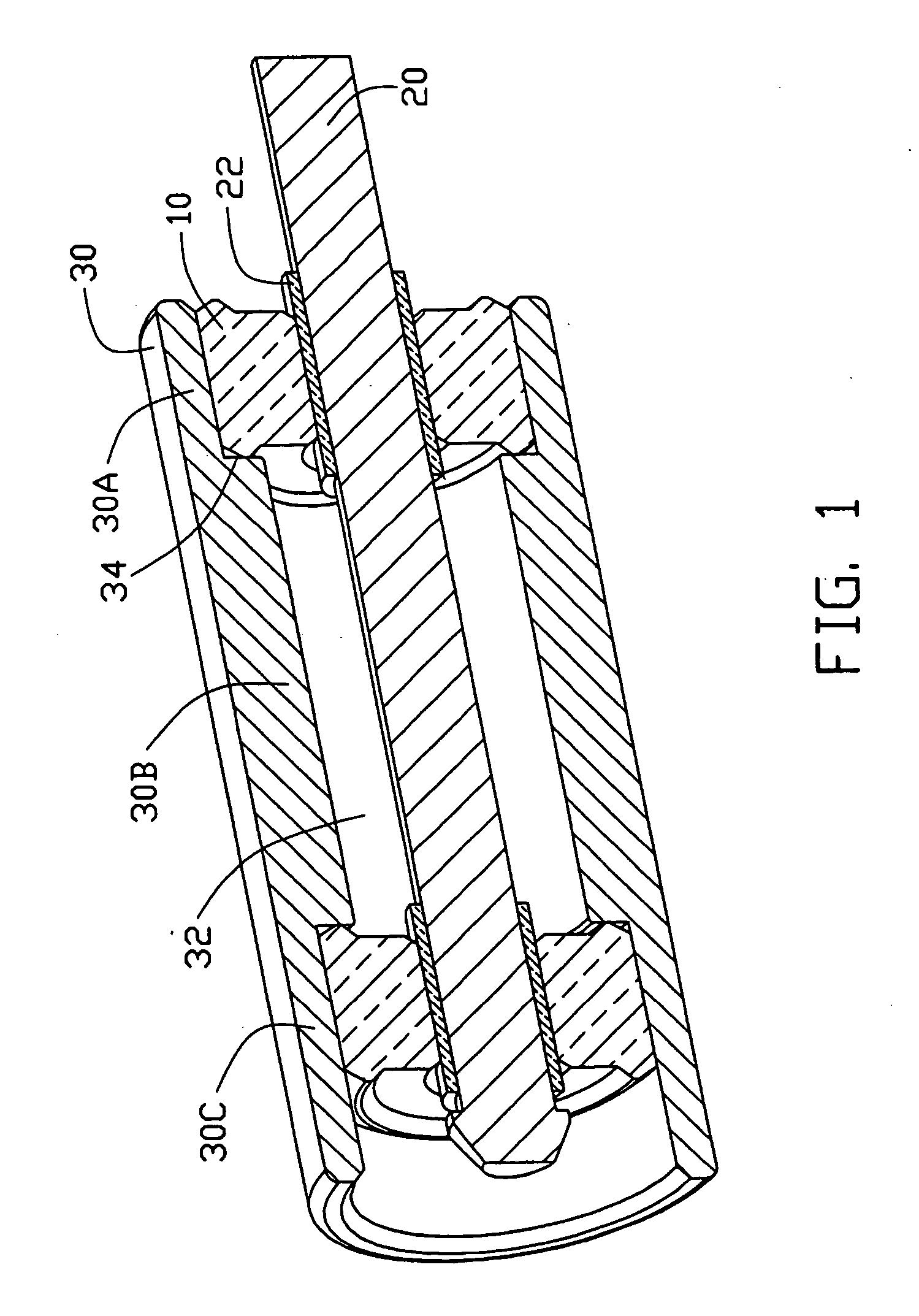
[0011] Referring to FIG. 1, a bearing assembly comprises a tube 30, a pair of radial bearings 10 fixed in the tube 30 at opposite ends thereof, and a shaft 20 supported by the radial bearings 10.

[0012] The tube 30 has an axial inner hole 32 for receiving the radial bearings 10 therein. The tube 30 comprises opposite end sections 30A, 30C, and a middle section 30B. The diameter of the inner hole 32 at the end sections 30A, 30B of the tube 30 is greater than that at the middle section 30B of the tube 30, so that a pair of annular inner steps 34 is formed between the middle section 30B and the end sections 30A, 30C of the tube 30 respectively.

[0013] The radial bearings 10 are sleeve bearings, and are fitted in the end sections 30A, 30C of the tube 30. The radial bearings 10 are engaged with the inner steps 34 to prevent axial movement thereof. Each radial bearing 10 defines an inner bearing surface (not labeled) concentric with the inner hole 32 of the tube 30.

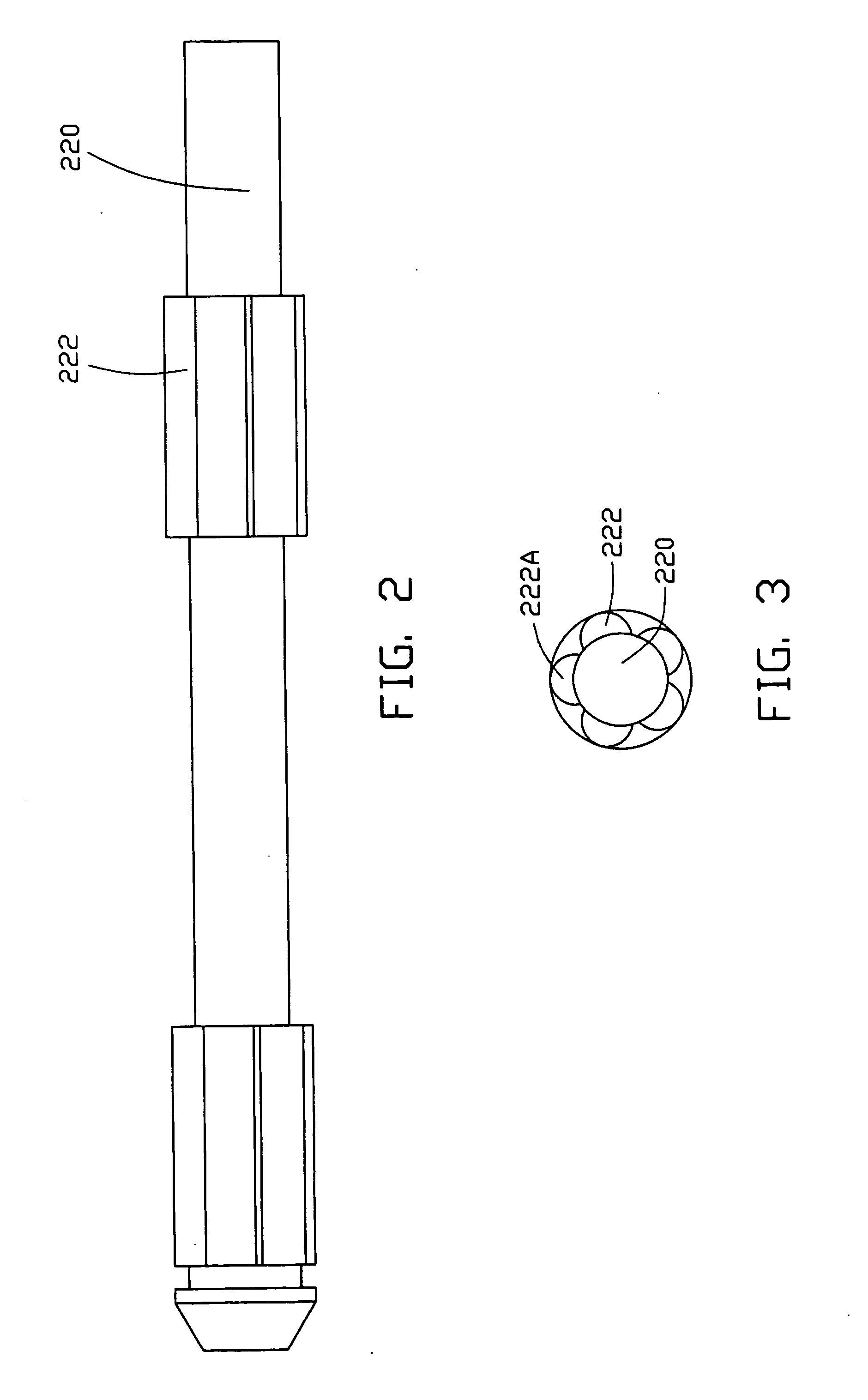
[0014] The shaft 20 is...


PUM


Abstract

A bearing assembly includes a tube (30) axially defining an inner hole (32), a radial bearing (10) fixed in the inner hole of the tube and having an inner bearing surface concentric with the inner hole, and a shaft (20) pivotably received the inner hole. The shaft comprises a contact portion (22, 220) circumferentially formed at an outer periphery thereof confronting with the inner bearing surface of the bearing. The contact portion comprises an outer bearing surface being configured to have a substantially same abrasive resistance with the bearing surface to reduce wear thereon.

Description

TECHNICAL FIELD [0001] The present invention relates generally to bearing assemblies, and more particularly, to bearing assemblies having improved wear-resistant ability for use in computer cooling fans or disk drives. BACKGROUND [0002] In recent years, magnetic recording devices such as hard disk drives, floppy disk drives, optical recording devices such as CD-ROMs, DVD-ROMs, and computer cooling fans have made a remarkable development. In any one of such electronic equipments, a disk or a flow impeller is mounted to a shaft. A rotational driver such as an electrical motor rotates the shaft with a high speed. The disk or the flow impeller is thus driven to rotate with the shaft for reading / writing data or moving flow. [0003] Also, in any one of such electronic equipments, the shaft is supported by a bearing member. During rotation, the outer surface of the shaft slidingly contacts with a bearing surface of the bearing member. This will inevitably cause wear on the outer surface of ...

Claims


Application Information

Patent Timeline
Patent Type & Authority Applications(United States)
IPC IPC(8): F16C17/02F16C17/26F16C33/04F16C33/06
CPCF16C17/02F16C33/06F16C33/043F16C17/26
Inventor KU, CHIN-LONGYEH, CHIN-WENYANG, CHIH-HAO
Owner HON HAI PRECISION IND CO LTD
Why Eureka
Try Eureka