Abutment of implant system

a technology of implant system and abutment, which is applied in the field of abutment of implant system, can solve the problems of high cost of fabrication and its cost, complicated operation method, and many complications, and achieve the effects of enhancing the contact state of the surface, convenient holding, and convenient operation work

Inactive Publication Date: 2005-07-14
CHANG SANG KOHN
View PDF5 Cites 15 Cited by
  • Summary
  • Abstract
  • Description
  • Claims
  • Application Information

AI Technical Summary

Benefits of technology

[0016] It is another object of the present invention to provide an abutment of an implant system capable of achieving an escape groove of air compressed in an assembling hole in such a manner that a circular rim groove is formed at a post part of an abutment.
[0017] It is further another object of the present invention to provide an abutment of an implant system capable of enhancing a surface contacting state in such a manner that a certain flexibility is provided at an upper side and a lower side of a post part.
[0018] It is still further another object of the present invention to provide an abutment of an implant system capable of achieving an easier operation work in such a manner that it is easy to hold using a tool or a jig when an abutment is inserted into and is pulled out from a fixture.

Problems solved by technology

The screw type implant system needs many parts, and a fabrication and its cost are too expensive, and an operation method is so complicated.
Many complications may occur.
The cost that a patient pays is too high.
The clearances formed due to a bad connection state between a fixture and an abutment may be ways through which various bacteria are penetrated for thereby causing hygienic problems.
In addition, inflammations may occur at a surrounding tissue.
In this case, it is impossible to fabricate a full conical structure.
Namely, since it is impossible to achieve a fill conical structure, the contacting portions of the upper and lower sides may be unnatural.
Various bacteria may penetrate into the clearances, resulting in a bad tooth health.
In the conventional art, the conventional abutment does not have a proper portion for fixing the same, so that the operation is very difficult.

Method used


Image

  • Abutment of implant system
  • Abutment of implant system
  • Abutment of implant system

Examples


Embodiment Construction

[0024] The preferred embodiments of the present invention will be described with reference to the accompanying drawings.

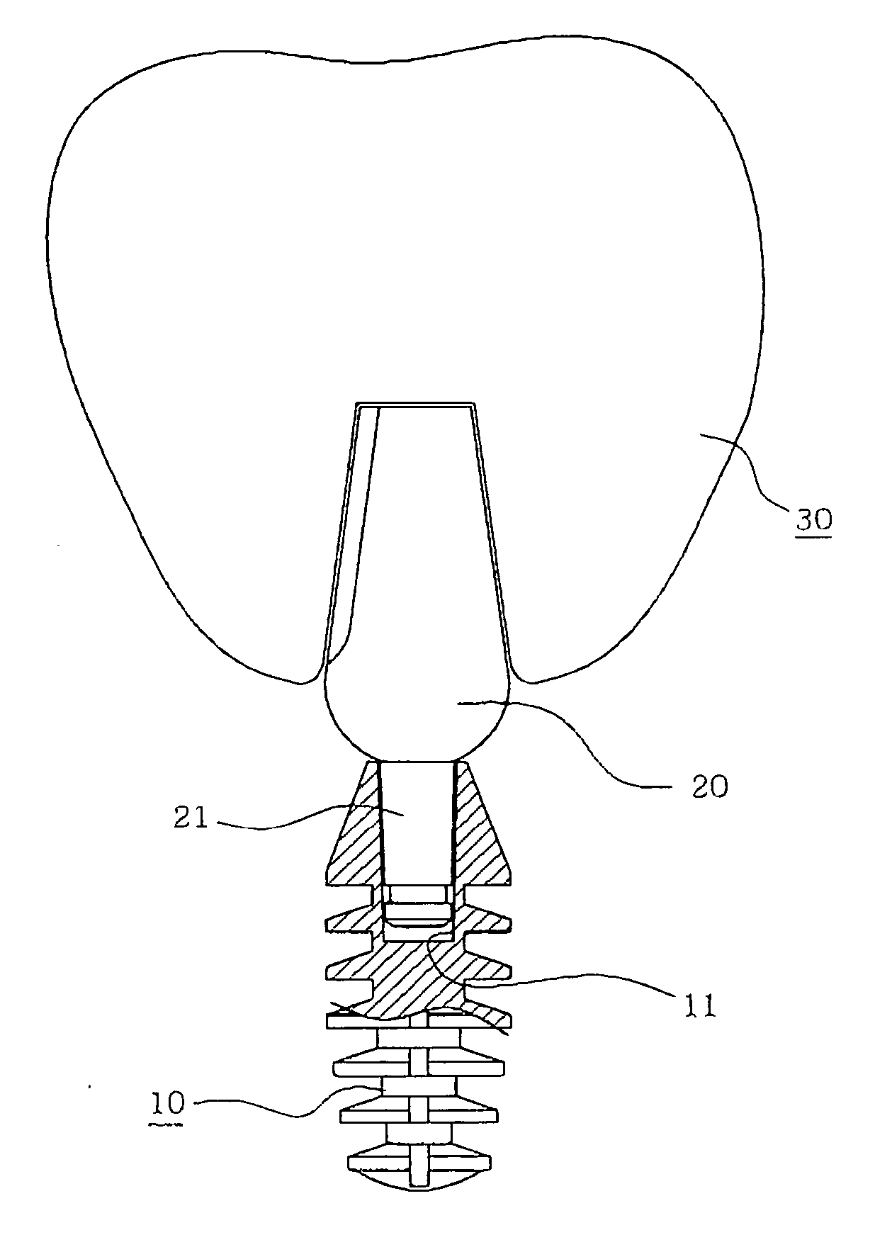
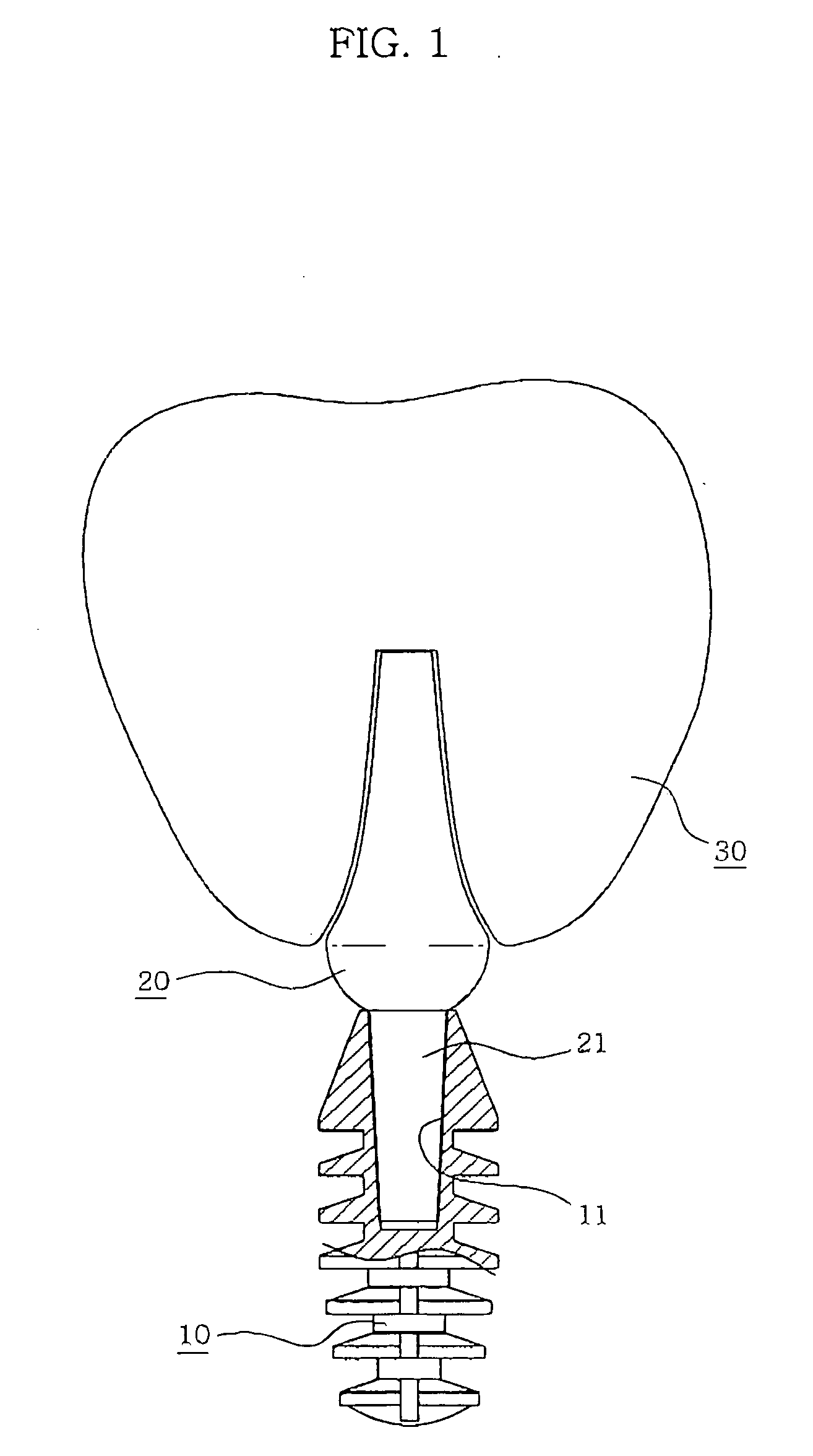
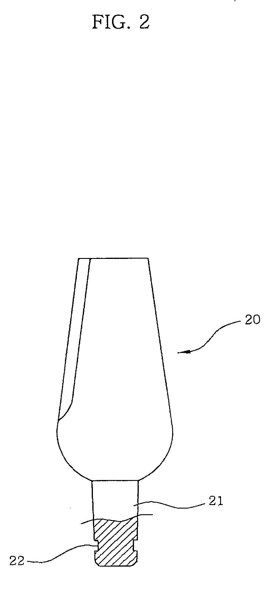
[0025]FIG. 2 is a cross sectional view illustrating an abutment according to the present invention, and FIG. 3 is a cross sectional view illustrating the entire implant system including an abutment according to the present invention.

[0026] As shown therein, the implant system includes a fixture 10 having a taper assembling hole 11 at an upper surface, an abutment 20 having a taper post part 21 inserted into the assembling hole 11 of the fixture, and a restoration 30 assembled to an upper side of the abutment.

[0027] In the present invention, at least one circular rim groove 22 is formed at the post part 21. Namely, the post part 21 is formed at the abutment 20 so that it is inserted into the assembling hole 11 of the fixture 11, and a circular rim groove 22 is formed at an outer surface of the lower side of the intermediate portion of the post part 21.

[0028] As ...


PUM


Abstract

The present invention relates to an abutment of an implant system. It is a primary object of the present invention an abutment of an implant system capable of achieving an escape groove of air compressed in an assembling hole in such a manner that a circular rim groove is formed at a post part of an abutment. In addition, it is capable of enhancing a surface contacting state in such a manner that a certain flexibility is provided at an upper side and a lower side of a post part. An easier operation work can be achieved in such a manner that it is easy to hold using a tool or a jig when an abutment is inserted into and is pulled out from a fixture. To achieve the above objects, in an implant system that includes a fixture having a taper assembling hole at an upper surface, an abutment having a taper post part so that it is inserted into the assembling hole of the fixture, and a restoration assembled to an upper side of the abutment, there is provided an abutment of an implant system comprising at least one circular rim groove formed at an outer surface of a lower side of an intermediate portion wherein the post part is assembled into the assembling hole.

Description

BACKGROUND OF THE INVENTION [0001] 1. Field of the Invention [0002] The present invention relates to an abutment of an implant system, and in particular to an improved abutment of an implant system capable of enhancing an assembled state when an assembling hole of a fixture is assembled and achieving an easier operation in such a manner that a post part of an abutment is improved. [0003] 2. Description of the Background Art [0004] Generally, in an implant system, a fixture is inserted into an alveolar and is osseointegrated with a bone, and an abutment adapted to support an implant is engaged with the fixture. A restoration is covered on the abutment. In the above implant, it is possible to independently plant one tooth. Since the thusly planted implant has a self-support function, so that it is not needed to cut a neighboring tooth for the damaged (removed) teeth. In a certain situation, it is possible to stably fix an artificial tooth. The implant has a long life span and a good l...

Claims


Application Information

Patent Timeline
Patent Type & Authority Applications(United States)
IPC IPC(8): A61C8/00
CPCA61C8/0018A61C8/0069A61C8/005A61C8/00
Inventor CHANG, SANG-KOHN
Owner CHANG SANG KOHN
Why Eureka
Try Eureka