Polymer electrolyte fuel cell

a technology of polymer electrolyte and fuel cell, which is applied in the direction of fuel cell details, electric generators, fuel cells, etc., can solve the problems of failure to prevent the inflow of molten resin into the porous member, the disclosure measures are not perfect, and the efficiency of electricity generation in the fuel cell is affected, so as to avoid the drop in electricity generation performance, reduce the area of press-working, and improve productivity

Inactive Publication Date: 2010-03-04
TOYOTA SHATAI KK +1
View PDF2 Cites 7 Cited by
  • Summary
  • Abstract
  • Description
  • Claims
  • Application Information

AI Technical Summary

Benefits of technology

[0007]The present invention has been achieved for solving the above problems, and an object of the invention is to provide a polymer electrolyte fuel cell having collectors which are formed from a porous material and with which a resin seal member is formed integrally in such a manner that inflow of a molten resin into the collectors is reliably prevented.
[0014]According to a further feature of the present invention, the resin seal member formed by the insert molding has a thickness substantially equal to a thickness of a central portion of each of the collectors. This facilitates an operation of assembling (e.g., bonding) the membrane-electrode assembly and the collector having the integrally formed resin seal member together and an operation of assembling (e.g. bonding) the collector and the separator together. In this case, more preferably, the thickness of the resin seal member formed by the insert molding is slightly smaller than the thickness of a central portion of the collector. This establishes a good state of contact between the membrane-electrode assembly and the collector and that between the collector and the separator. This reduces resistance associated with collection, by each of the collectors, of electricity generated through electrode reactions in the membrane-electrode assembly and resistance associated with conduction of collected electricity from each of the collectors to the corresponding separator. As a result, output from the fuel cell can be favorably maintained.

Problems solved by technology

However, generally, in the case where a resin portion is formed integrally with a porous member through injection of a molten resin, the molten resin flows into the porous member in the course of molding, possibly filling a large number of pores formed in the porous member.
As a result, introduced fuel gas and oxidizing gas may fail to be favorably supplied to a membrane-electrode assembly (MEA), potentially causing a drop in the efficiency of electricity generation in the fuel cell.
However, the disclosed measures are not perfect.
In such a case, the fluidity of the molten resin cannot be properly controlled, resulting in a possible failure to prevent inflow of the molten resin into the porous member.

Method used


Image

  • Polymer electrolyte fuel cell
  • Polymer electrolyte fuel cell
  • Polymer electrolyte fuel cell

Examples


Embodiment Construction

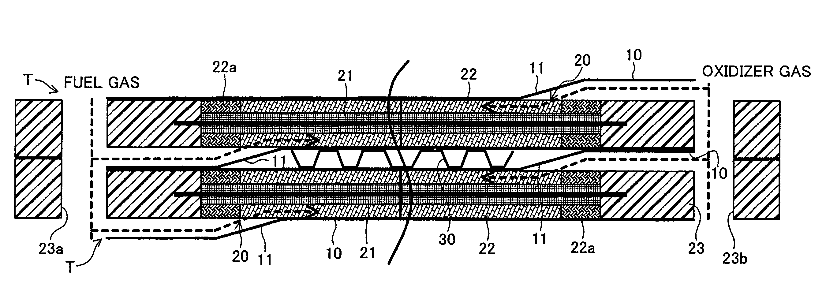
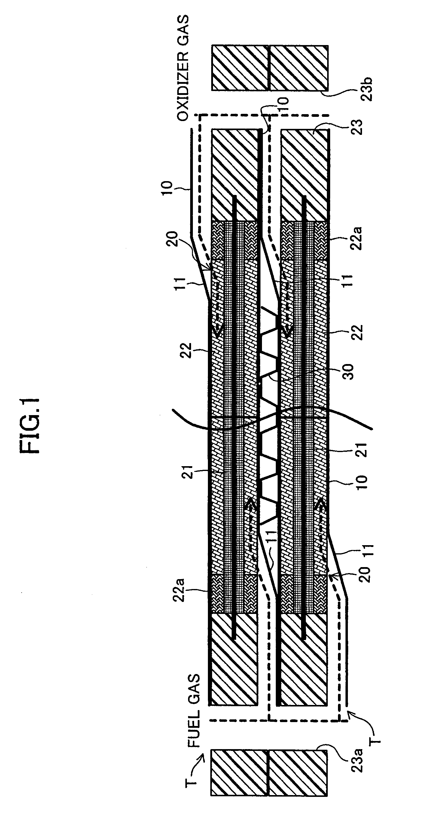
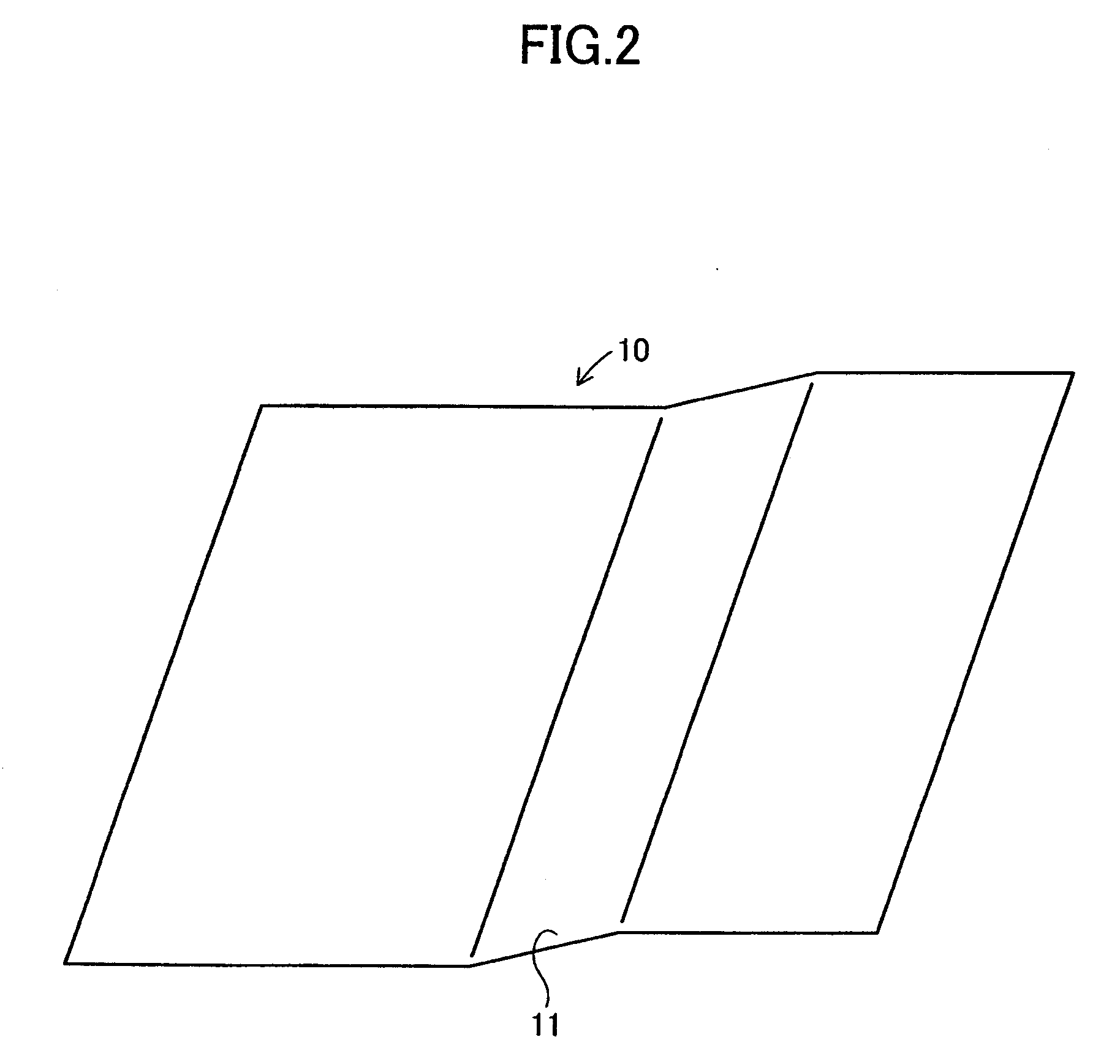
[0028]An embodiment of the present invention will next be described in detail with reference to the drawings. FIG. 1 is a sectional view schematically showing a portion of a polymer electrolyte fuel cell stack according to an embodiment of the present invention. The fuel cell stack has cells T. Each of the cells T includes a pair of fuel cell separators 10 (hereinafter, referred to merely as separator(s) 10) and an electrode structure 20 disposed between the separators 10. The fuel cell stack is configured such that a large number of the cells T are stacked while cooling water channels 30 are sandwiched between the cells T.

[0029]In the thus-configured fuel cell stack, fuel gas, such as hydrogen gas, and oxidizer gas, such as air, are externally introduced to the cells T, thereby generating electricity through electrode reactions in the electrode structures 20. Hereinafter, fuel gas and oxidizer gas may be collectively called gas.

[0030]The separators 10 are adapted to supply gas to t...


PUM

PropertyMeasurementUnit
diameteraaaaaaaaaa
thicknessaaaaaaaaaa
diameteraaaaaaaaaa

Abstract

Each of collectors 22 of an electrode structure 20, which partially constitutes a polymer electrolyte fuel cell, is formed from a metal lath MR having a large number of through-holes. A stopping portion 22a in which the through-holes are reduced in diameter is formed at a peripheral end portion of the collector 22. The peripheral end portion of the collector 22 is folded; subsequently, the folded peripheral end portion is pressed, thereby forming the stopping portion 22a. A resin seal portion 23 for sealing introduced fuel gas and oxidizer gas is formed integrally with the stopping portions 22a by insert molding which is performed such that an injected molten resin encloses the stopping portions 22a. The resin seal portion 23 formed integrally with the stopping portions 22a can reliably prevent inflow of the molten resin toward central portions of the collectors 22.

Description

TECHNICAL FIELD[0001]The present invention relates to a fuel cell, and more particularly to a polymer electrolyte fuel cell.BACKGROUND ART[0002]Conventionally known polymer electrolyte fuel cells are disclosed in, for example, Japanese Patent Application Laid-Open (kokai) Nos. 2002-184422 and 2005-317322. The conventional polymer electrolyte fuel cells employ a cell structure. In the cell structure, a membrane-electrode assembly (MEA) and metal plates having projections (or collectors having channels) are disposed between two carbon plates (or two separator plates); the membrane-electrode assembly (MEA) includes an electrolyte membrane (electrolyte), an anode electrode, and a cathode electrode; and a seal (frame) is disposed around the metal plates (or collectors). In the cell structure, a space is defined by a surface of the membrane-electrode assembly (MEA), an inner peripheral wall of the seal (frame), and a surface of each of the carbon plates (separator plates). The metal plate...

Claims


Application Information

Patent Timeline
Patent Type & Authority Applications(United States)
IPC IPC(8): H01M8/10
CPCH01M8/0232Y02E60/50H01M2008/1095H01M8/0284H01M8/02H01M8/10
Inventor KAWAJIRI, KOUSUKETANAKA, HIDETOTAKAMURA, TOMOYUKISHINOZAKI, YOSHINORIIIZUKA, KAZUTAKAWADA, MIKIOKATO, CHISATOKANAI, NOBUO
Owner TOYOTA SHATAI KK
Why Eureka
Try Eureka