Bevel and depth of cut detent system

a detent system and bevel technology, applied in the field of power tools, can solve the problem of taking time and care to get the desired setting accurately

Active Publication Date: 2005-07-21
CREDO TECH CORP +1
View PDF13 Cites 25 Cited by
  • Summary
  • Abstract
  • Description
  • Claims
  • Application Information

AI Technical Summary

Benefits of technology

[0005] A first preferred embodiment that is particularly useful in a depth of cut detent system utilizes a bracket having an arcuate slot therein with enlarged portions at the detent locations which enlarged portions generally encompass a circular shape that has a diameter that is slightly larger than the width of the slot at each detent location and wherein a locking member has a washer with a diameter larger than the width of the slot and the enlarged portions. The washer has a truncated conical extension adjacent an

Problems solved by technology

Professional users often adjust the bevel and depth setting on circular saws, miter s

Method used


Image

  • Bevel and depth of cut detent system
  • Bevel and depth of cut detent system
  • Bevel and depth of cut detent system

Examples


Embodiment Construction

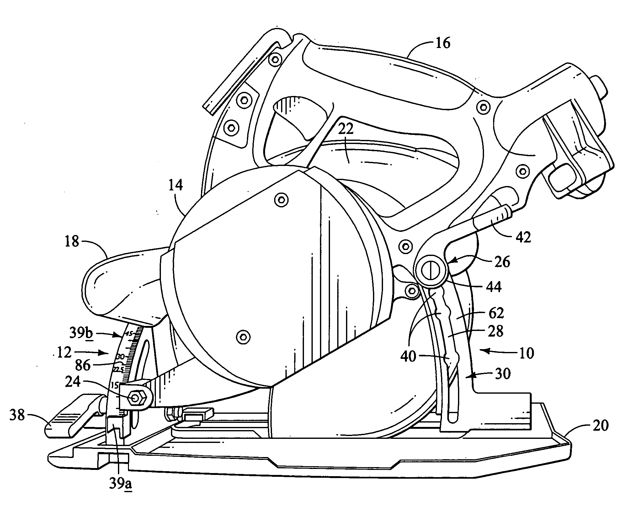
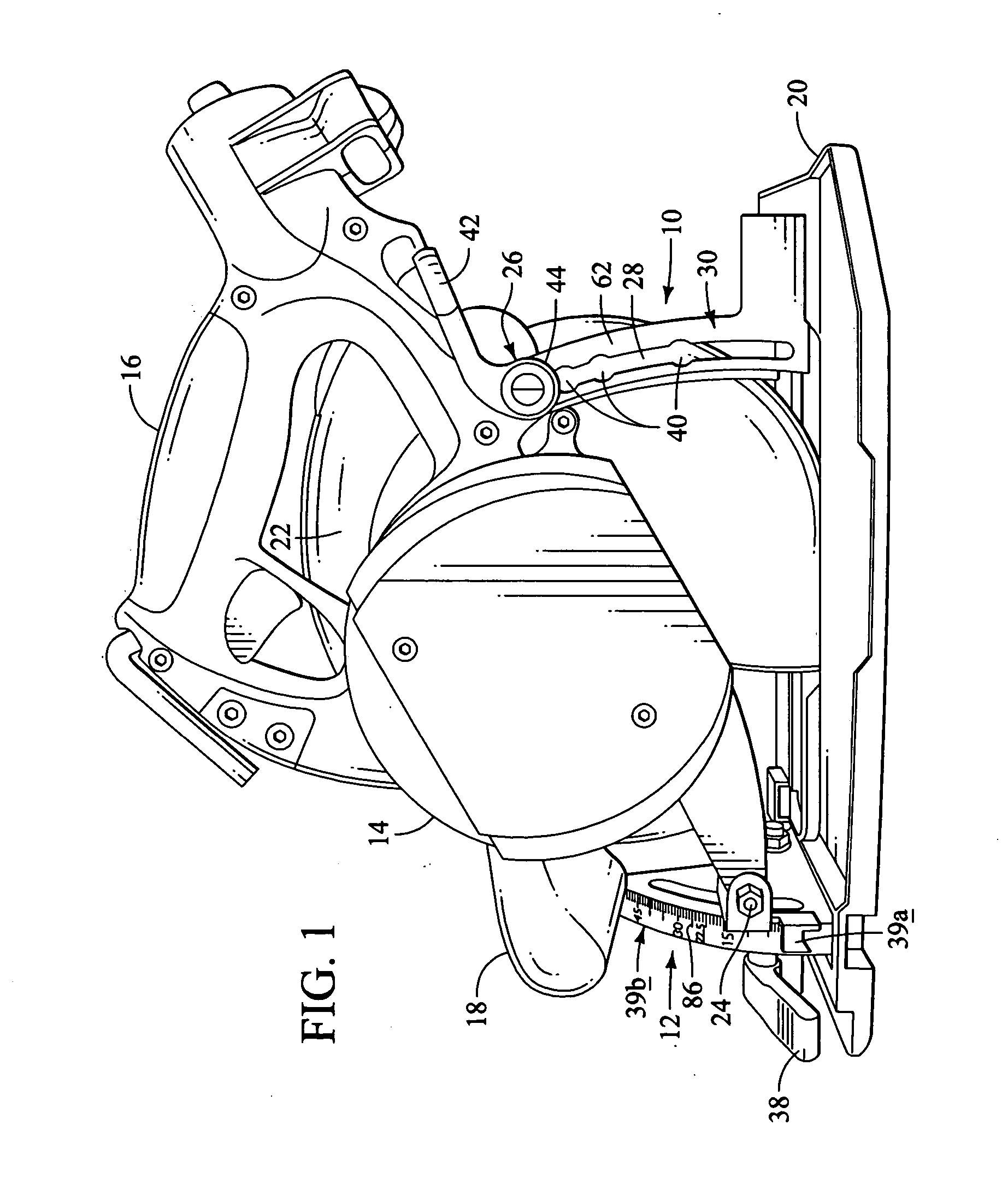
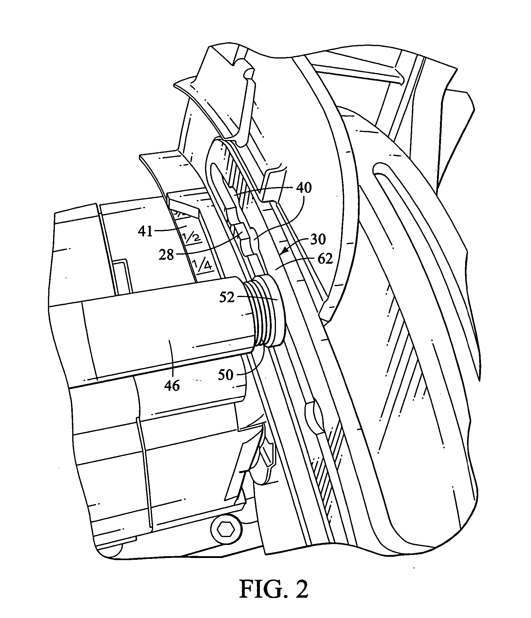
[0021] There are two preferred embodiments that are shown in the drawings in connection with a circular saw. The first preferred embodiment is a depth of cut detent system that is used to quickly sense and adjust the amount by which the saw blade extends below the foot portion of the saw that effectively determines the depth of cut that can be made by the saw. The second preferred embodiment is directed to a bevel detent system that is provided with the circular saw to vary the bevel angle of the saw to a predetermined angle.

[0022] While the preferred embodiments are shown in connection with a circular saw, it should be understood that the detent systems that are disclosed and described herein may be used with other hand tools or other types of mechanisms where detents are used to define desired commonly used positions for a mechanism and where a locking capability is desired to hold the mechanism in a desired position.

[0023] Turning now to the drawings, and particularly FIG. 1, a...


PUM

PropertyMeasurementUnit
Angleaaaaaaaaaa
Lengthaaaaaaaaaa
Forceaaaaaaaaaa

Abstract

A circular saw assembly of the type that includes a motor housing, a handle coupled to the motor housing, a generally circular saw blade disposed within a blade housing at a first end of the motor housing, and a foot member through which the blade extends for guiding the saw assembly along a work surface, where the circular saw assembly including a depth of cut locking system and an angle of cut locking system. The depth of cut locking system includes an arcuate bracket with an arcuate slot, and an engagement member extends through the slot and is operatively connected to the motor housing and slideable in the arcuate slot. The angle of cut locking system includes a bracket having an arcuate slot and an engagement member movable in the slot and configured to the bracket. A biasing member is provided to bias the engagement member, and at least one detent recess is provided to retain the engagement member therein.

Description

[0001] This application claims the benefit under 35 U.S.C. §119 of U.S. Provisional Application No. 60 / 537,436, filed on Jan. 16, 2004.BACKGROUND OF THE INVENTION [0002] The present invention generally relates to power tools and particularly to power hand tools. [0003] The power hand tools such as miter saws, circular saws, as well as other hand tools are often provided with the capability of adjusting the depth of cut or the bevel angle. Where such adjustability is provided in a tool, there is generally a measurement display and indicator present on the tool that will enable the user to set the angle or depth of cut at the desired location after which a locking lever is generally tightened to hold the tool in its desired position. Professional users often adjust the bevel and depth setting on circular saws, miter saws and other tools, which takes time and care to get the desired setting accurately. Because there are common angles such as 22½° and 45° for bevel angles, and particula...

Claims


Application Information

Patent Timeline
IPC IPC(8): B27B9/02
CPCB27B9/02Y10T403/32377Y10T403/599Y10T403/32541Y10T403/606
Inventor HARTMANN, JAMES R.BOCKA, RALFWASCOW, JOSEPH Z.
Owner CREDO TECH CORP
Why Eureka
Try Eureka