Hand-operated circular saw having blade cutting depth adjustment device

a technology of depth adjustment and hand-operated circular saws, which is applied in the direction of metal sawing devices, metal sawing accessories, manufacturing tools, etc., can solve the problems of difficulty in cutting on the table type cutting machine, the rapid rotation of the saw blade may unintentionally hurt people or the user himself, and the difficulty of hand-operated circular saws. to achieve the effect of convenient, quick operation, and convenient and precise operation

Inactive Publication Date: 2005-07-21
CHEN YUEHTING
View PDF6 Cites 22 Cited by
  • Summary
  • Abstract
  • Description
  • Claims
  • Application Information

AI Technical Summary

Benefits of technology

This patent describes a small electric saw that can be easily handled and used on different surfaces like tables or walls. It includes a movable lower plate that controls how deep the saw cuts into the material. There are also pivots and springs built into the design that make it easy to control the angle of the saw. Overall, this little machine allows users to have complete precision when making their own custom cuts.

Problems solved by technology

The technical problem addressed in this patent is the difficulty of accurately cutting working objects with conventional table-type cutting machines, and the potential danger of hand-operated circular saws due to unintentional injury or lack of proper guarding. The patent proposes a solution in the form of a hand-operated circular saw with blade cutting depth adjustment device that can lean on a wall, table, or ground for precise cutting.

Method used


Image

  • Hand-operated circular saw having blade cutting depth adjustment device
  • Hand-operated circular saw having blade cutting depth adjustment device
  • Hand-operated circular saw having blade cutting depth adjustment device

Examples


Embodiment Construction

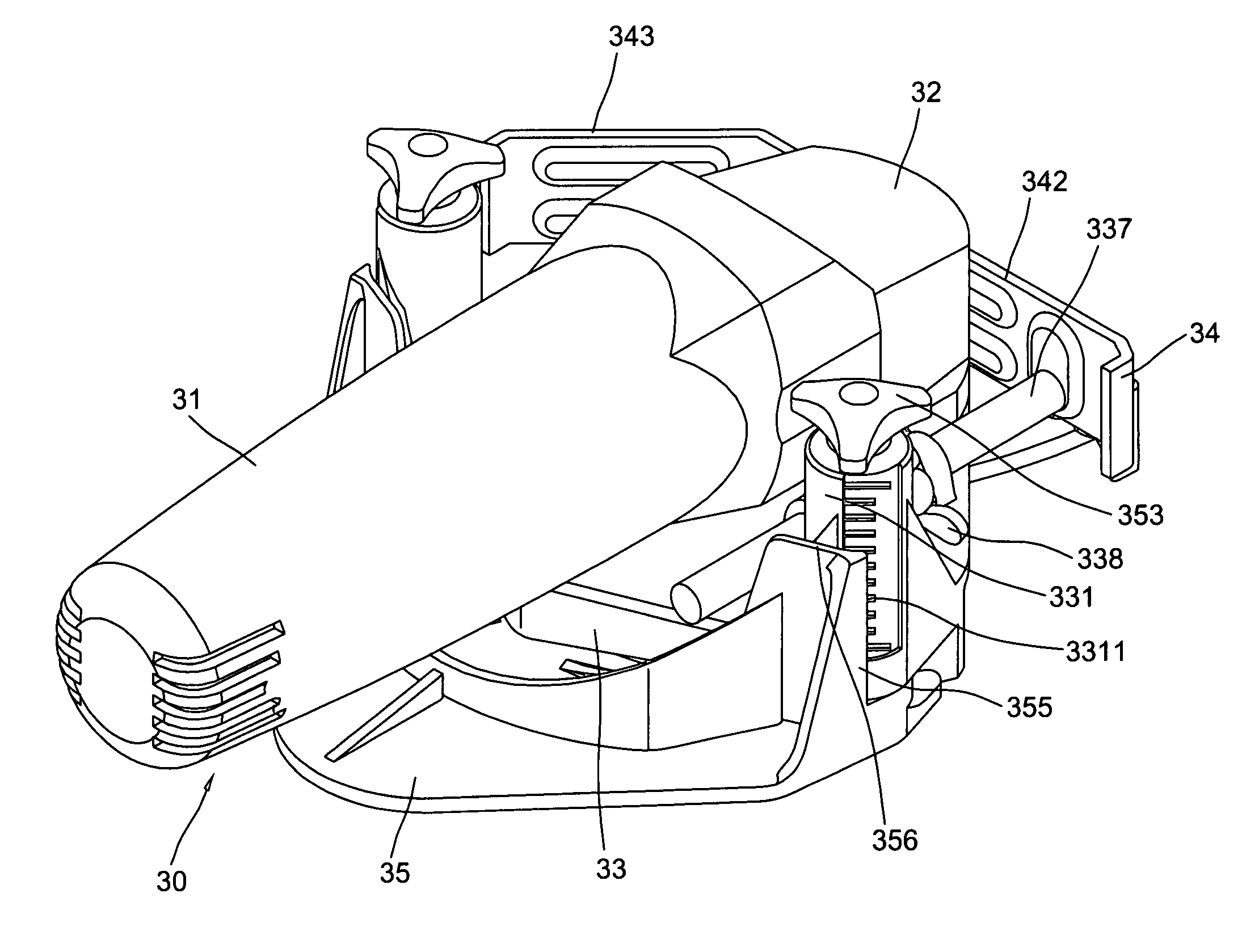
[0019] With reference to the drawings and initiated from FIGS. 4, 5 and 6, the hand-operated circular saw having blade cutting depth adjustment device of the present invention comprises a hollow interior tubular body 30 having a hand grasp portion 31, a head portion 32 which includes a threaded axis 321 extruded out from one lateral side operated by, a motor (not shows) embedded therein and a plurality of screw holes 322 spacedly formed in the head portion 32 around a circular protrusion for securing an upper plate 33 by a plurality of screws 323, which has a protrudent circular hole 330 in a plane porting engaged on the circular protrusion, a pair of pivotal tubes 331 spacedly projected upward for respectively receiving a pair of springs 351, a pair of internally threaded cylinder rods 352 for engaging with a pair of quickly operated bolts 353 in the top and connected with a lower plate 35 in the bottom by a pair of screws 354 through a pair of through holes 358 in the lower plate ...


PUM

PropertyMeasurementUnit
Depthaaaaaaaaaa

Abstract

A hand-operated circular saw having blade cutting dap the adjustment device includes a hallow interior tubular body having a hand grasp portion, a head portion, a motor disposed in the head portion to operate a threaded axis protrude from a threaded circular protrusion on a outer side of the head, an upper plate secured to the outer side including a circular hole engaged with the circular protrusion, a pair of pivotal tubes and a pair of horizontal arc protrusion on the top, a guard plate, a pad ring, an internally thread tube and a saw blade sequentially secured to the axis, a lower plate connected to a pair of cylinder rods inside the pivotal tube, a pair of quickly operated bolt in the top of the pivotal tubes for adjusting the vertical positions of the lower plate and the saw blade, a bent lateral slidably engaged within the horizontal arc protrusion through a pair of elongate cylinder rod for adjusting the cutting depth of the saw blade and a U-shaped handle pivoted to the head portion of the tubular body.

Description


Claims


Application Information

Patent Timeline
Owner CHEN YUEHTING
Why Eureka
Try Eureka