
Electronic musical instrument

Active Publication Date: 2005-07-21
YAMAHA CORP
View PDF7 Cites 4 Cited by
  • Summary
  • Abstract
  • Description
  • Claims
  • Application Information

AI Technical Summary

Benefits of technology

[0007] It is an object of the present invention to provide an electronic musical instrument which can be designed compact in longitudinal size and is excellent in acoustic characteristics.
[0009] With the above construction, the speaker box is configured to serve as a rear leg. Therefore, the speaker box itself can be designed large in vertical size, and hence, even if the speaker box is designed compact in longitudinal size, the volume of the speaker box can be increased, leading to good acoustic characteristics, such as the expansion of a reproducible low frequency range. Thus, an electronic musical instrument can be provided which can be designed compact in longitudinal size and is excellent in acoustic characteristics. Moreover, by designing the speaker box compact in longitudinal size, the resulting electronic musical instrument does not give a feeling of oppression to the player. Further, it is no longer necessary to separately provide rear leg members and lateral side panels serving as legs disposed at the opposite lateral sides of the musical instrument.
[0011] With the above construction, the same effects as those of the first aspect of the present invention can be provided. Besides, compared with a conventional musical instrument in which a pedal device is mounted via a rod-like member which is hung down from a location at a long distance from the floor surface (for example, the lower surface of a keybed or a speaker box), the stability of the pedals can be enhanced, and the weight of the electrical circuit section-housing part placed on the housing box further increases the stability, making the pedals easy to operate.
[0013] With the above construction, the same effects as those of the first aspect of the present invention can be provided. Besides, satisfactory acoustic separation of sounds from the left and right speakers is realized by the existence of the electrical circuit section-housing part. Further, the mass of this part, i.e. the mass of an electrical circuit member such as the musical tone generating device, becomes large, which prevents acoustical interference between sounds from the left and right speakers, leading to improved low frequency range sound characteristics in particular.
[0015] With the above construction, the same effects as those of the first aspect of the present invention can be provided. Besides, since the horizontal plate-shaped bridging member spanning the left and right speakers is disposed at the lower parts of the left and right speakers, and the pedals for foot operations by the player is secured to the lower surface of the bridging member for free swinging motions, the upper parts of the left and right speakers serving as rear legs are necessarily fixed to a part of the musical instrument main body, e.g. the keybed, whereas the lower parts of the speaker boxes are fixedly placed on the floor surface due to the weights of the speaker boxes themselves, and hence the pedals are fixed in place at a location close to the lower parts of the speaker boxes, and hence the pedals are stabilized and can be stably operated. In addition, the mass of parts involving the horizontal plate-shaped bridging member increases, leading to good acoustic separation.
[0017] With the above construction, in addition to the construction according to the fourth aspect, the electrical circuit section-housing part is placed on the horizontal plate-shaped bridging member. As a result, the weight of the electrical circuit member further enhances the stability of the pedals and hence the stability of the entire musical instrument.

Problems solved by technology

Moreover, by designing the speaker box compact in longitudinal size, the resulting electronic musical instrument does not give a feeling of oppression to the player.

Method used


Image

  • Electronic musical instrument
  • Electronic musical instrument
  • Electronic musical instrument

Examples


Embodiment Construction

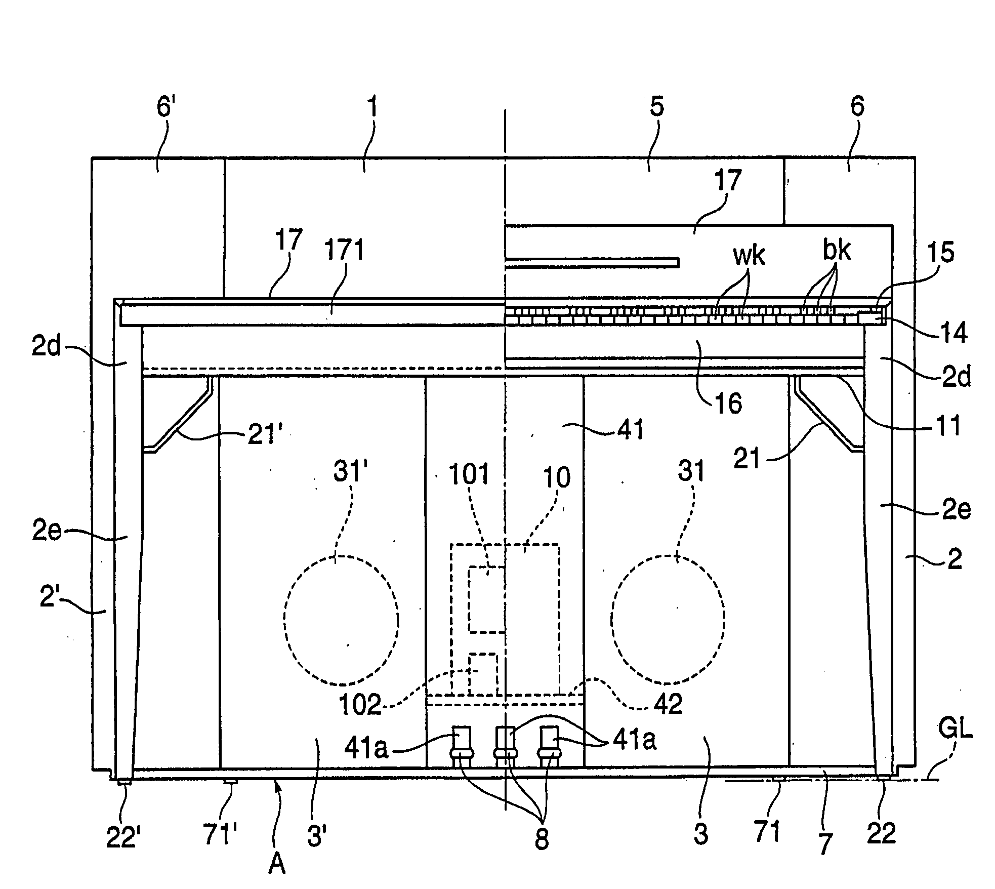
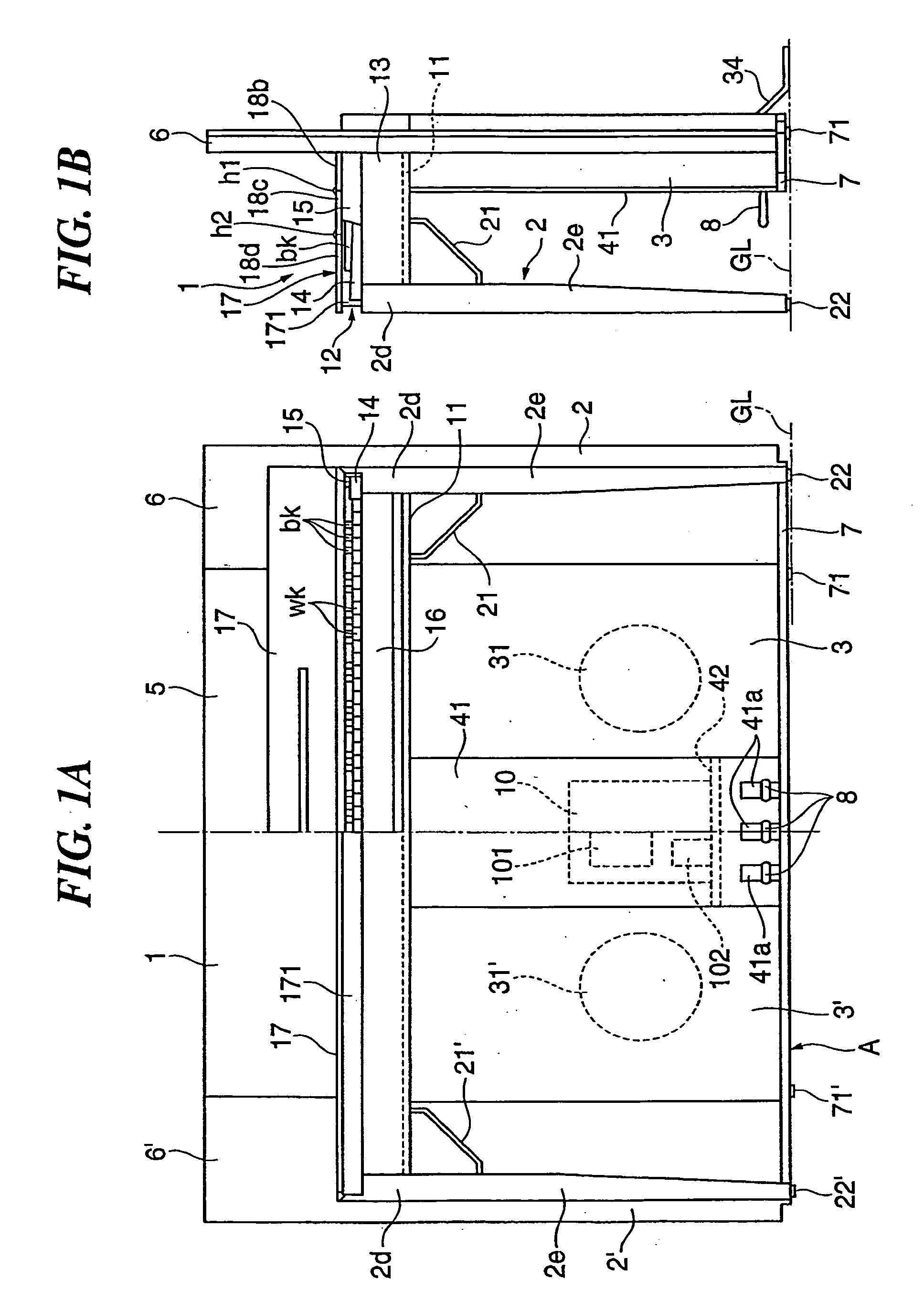
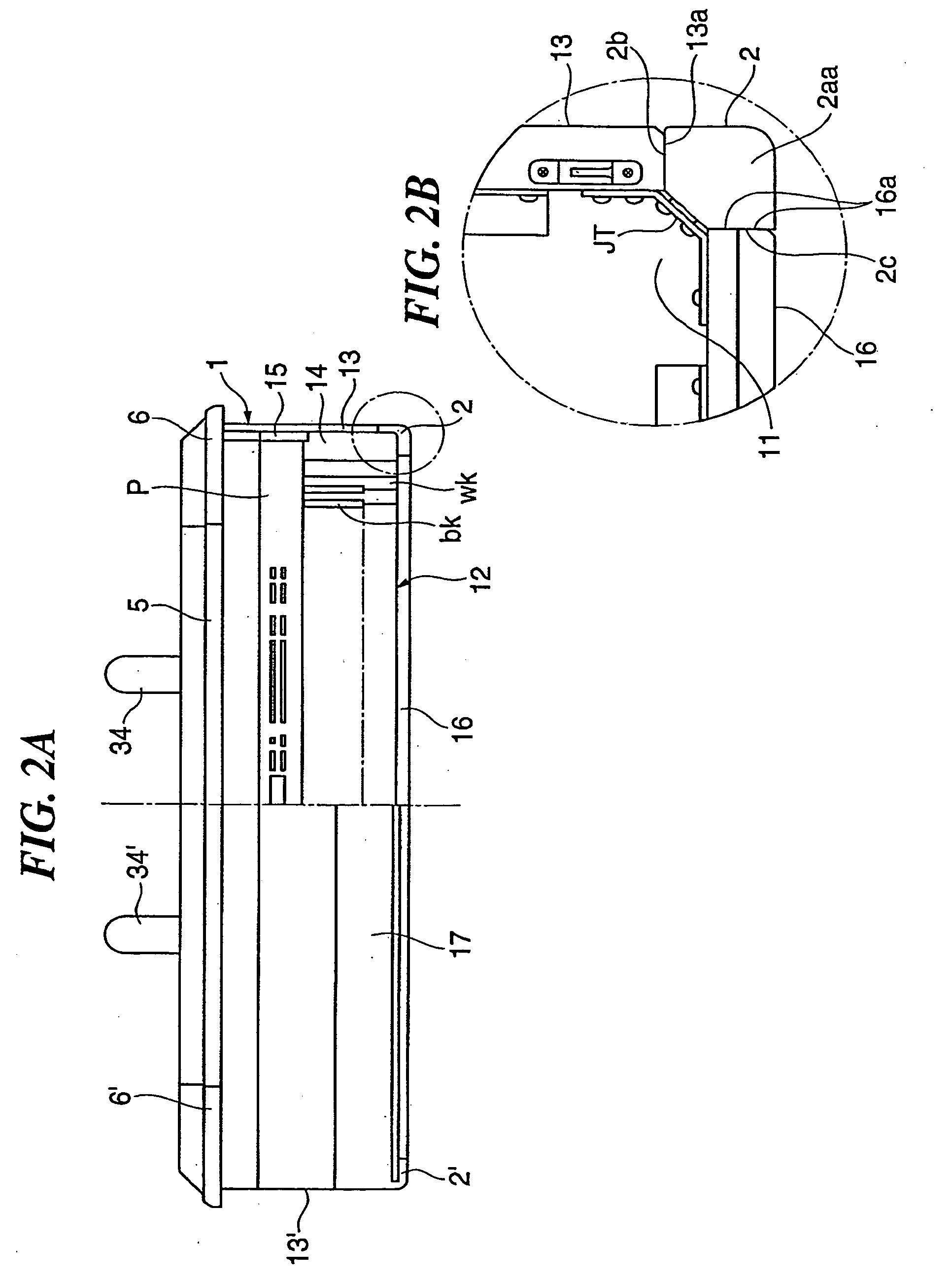
[0030] The present invention will now be described in detail with reference to the drawings showing a preferred embodiment thereof. In the drawings, elements and parts which are identical throughout the views are designated by identical reference numeral, and duplicate description thereof is omitted.

[0031] In the following description, for component elements each comprised of left and right halves, reference numeral for each of the left halves as viewed from the player is marked by an apostrophe ('), although all of them are not illustrated in the drawings.

[0032]FIG. 1A is a front view of an electronic musical instrument according to an embodiment of the present invention. FIG. 1B is a right side view of the electronic musical instrument. FIGS. 2A and 2B are top plan view of the electronic instrument, and FIG. 3 is a rear side view showing a support member appearing in FIG. 1 in an exploded state and useful in explaining the positional relationship between various component parts ...


PUM


Abstract

An electronic musical instrument which can be designed compact in longitudinal size and is excellent in acoustic characteristics. A musical instrument main body (1) has at least one keyboard device (12), and left and right lateral side panels (13 and 13′). A musical tone signal is generated by a controller (101) through operation of the keyboard device. The musical tone signal generated by the controller is acoustically converted by at least one speaker (31 or 31′). The musical instrument main body is supported by left and right front legs (2 and 2′) in the vicinity of the left and right lateral side panels of the musical instrument main body. An upper part of each front leg is secured to the musical instrument main body, and a lower part thereof extends to a floor surface on which the electronic musical instrument is placed. The speaker is held in a speaker box (3 or 3′). The speaker box serves as a supporting member that supports a rear side part of the musical instrument main body. The speaker box has a lower part extending to the floor surface to serve as a rear leg.

Description

BACKGROUND OF THE INVENTION [0001] 1. Field of the Invention [0002] The present invention relates to an electronic musical instrument which includes a musical tone signal generating device that generates a musical tone signal in response to performance operators, one or more speakers that convert the musical tone signal generated by the musical tone signal generating device into sound, and front legs that support the main body of the electronic musical instrument in the vicinity of left and right lateral side plates of the main body, and more particularly to an electronic musical instrument suitable for use as an electronic keyboard musical instrument equipped with a keyboard section at the main body thereof. [0003] 2. Description of the Related Art [0004] Conventionally, there has been proposed an electronic musical instrument in which the main body of the musical instrument is supported by a plurality of legs. In the musical instrument main body, a performance device (e.g. a keybo...

Claims


Application Information

Patent Timeline
IPC IPC(8): G10H1/00G10H1/32G10H3/00
CPCY10S84/17G10H1/32
Inventor FURUHASHI, TOMOHIRO
Owner YAMAHA CORP
Learn More