Composite Laminates Having Hole Patterns Produced by Controlled Fiber Placement

a technology of controlled fiber placement and composite laminates, which is applied in the field of composite laminates, can solve the problems of difficult removal from the cured laminate, high production cost, and time-consuming current techniques for forming a large number of perforations or holes, and achieves high repeatability and usefulness, improve acoustic properties of the laminate, and improve the effect of production ra

Inactive Publication Date: 2015-01-29
THE BOEING CO
View PDF3 Cites 23 Cited by
  • Summary
  • Abstract
  • Description
  • Claims
  • Application Information

AI Technical Summary

Benefits of technology

[0007]The disclosed embodiments provide a method of forming a pattern of holes in a composite laminate such as a skin used in acoustically treated panels for sound attenuation. Hole patterns may be formed in the laminate in situ as the laminate is being constructed. The need for specialized tooling such as pin mats is eliminated, and processes such as drilling and sandblasting which may produce fiber breakout are avoided. The method may be carried out using numerically controlled automatic fiber placement equipment, and is therefore efficient, highly repeatable and useful where higher production rates are desired. The method is also well-suited for use in fabricating composite laminates with controlled hole patterns using out-of-autoclave processes. In order to improve acoustic properties of the laminate, woven or non-woven materials such as, without limitation, metal or plastic wire meshes may be embedded into the laminate as the hole pattern is being formed.
[0009]According to another disclosed embodiment, a method is provided of producing a composite laminate layup having pattern of holes therein. A layup is formed by laying up multiple plies of unidirectional pre-preg fiber, wherein each of the plies is laid up by laying down bandwidths of pre-preg fiber tows. The method also includes spacing apart the tows in each of the bandwidths to form gaps between the tows as the bandwidths are being laid down, and controlling locations of the tows as the bandwidths are being laid down. The gaps between the tows are controlled as the bandwidths are being laid down, and the fiber orientations of the plies are varied to form a pattern of holes in the layup. Each of the plies is laid up using a numerically controlled automated fiber placement machine. Spacing the tows includes varying the gaps between the tows. The method may further comprise varying a width of the tows. At least one of a woven or a non-woven material may be embedded within the plies of the layup. The method may also include selecting hole locations, hole sizes and hole shapes, and programming an automated fiber placement machine to automatically layup the plies and vary the fiber orientations of the plies to form the pattern of holes. The method may further comprise curing the layup, and selecting a resin having a controlled flow characteristic that substantially prevents the resin from filling in the holes during the curing.
[0010]According to still another embodiment, a composite laminate is provided having a pattern of holes therein. The laminate comprises a plurality of spaced-apart fiber tows having varying fiber orientations arranged to form a pattern of holes in the laminate, and a resin matrix in which the fiber tows are embedded. The fiber tows are arranged in a plurality of plies having differing fiber orientations, and the fiber tows have varying widths. The holes each may have a polygonal shape. The resin matrix may be a thermally curable thermoset material or a thermoplastic, and possesses a flow characteristic that prevents the material from flowing into the holes during thermal curing.

Problems solved by technology

Current techniques for forming a large number of perforations or holes in a composite laminate can be time consuming, labor intensive and expensive.
The pins can be fragile and may be difficult to remove from the cured laminate.
Drilling thousands of individual holes with a drill bit is time consuming and may result in fiber breakout surrounding the holes due to bit wear.
The sandblasting process may also result in undesired fiber breakout.
Fiber breakout around a hole may cause the hole diameter, hole finish and / or edges of the hole to be out-of-tolerance.

Method used


Image

  • Composite Laminates Having Hole Patterns Produced by Controlled Fiber Placement
  • Composite Laminates Having Hole Patterns Produced by Controlled Fiber Placement
  • Composite Laminates Having Hole Patterns Produced by Controlled Fiber Placement

Examples


Embodiment Construction

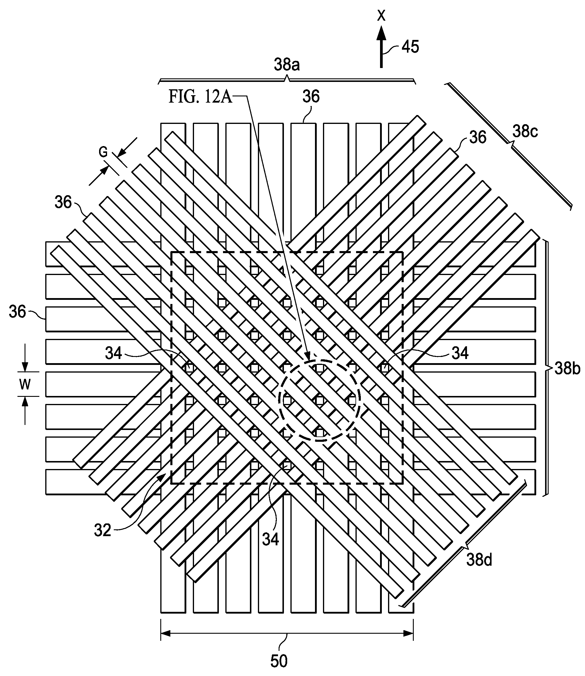
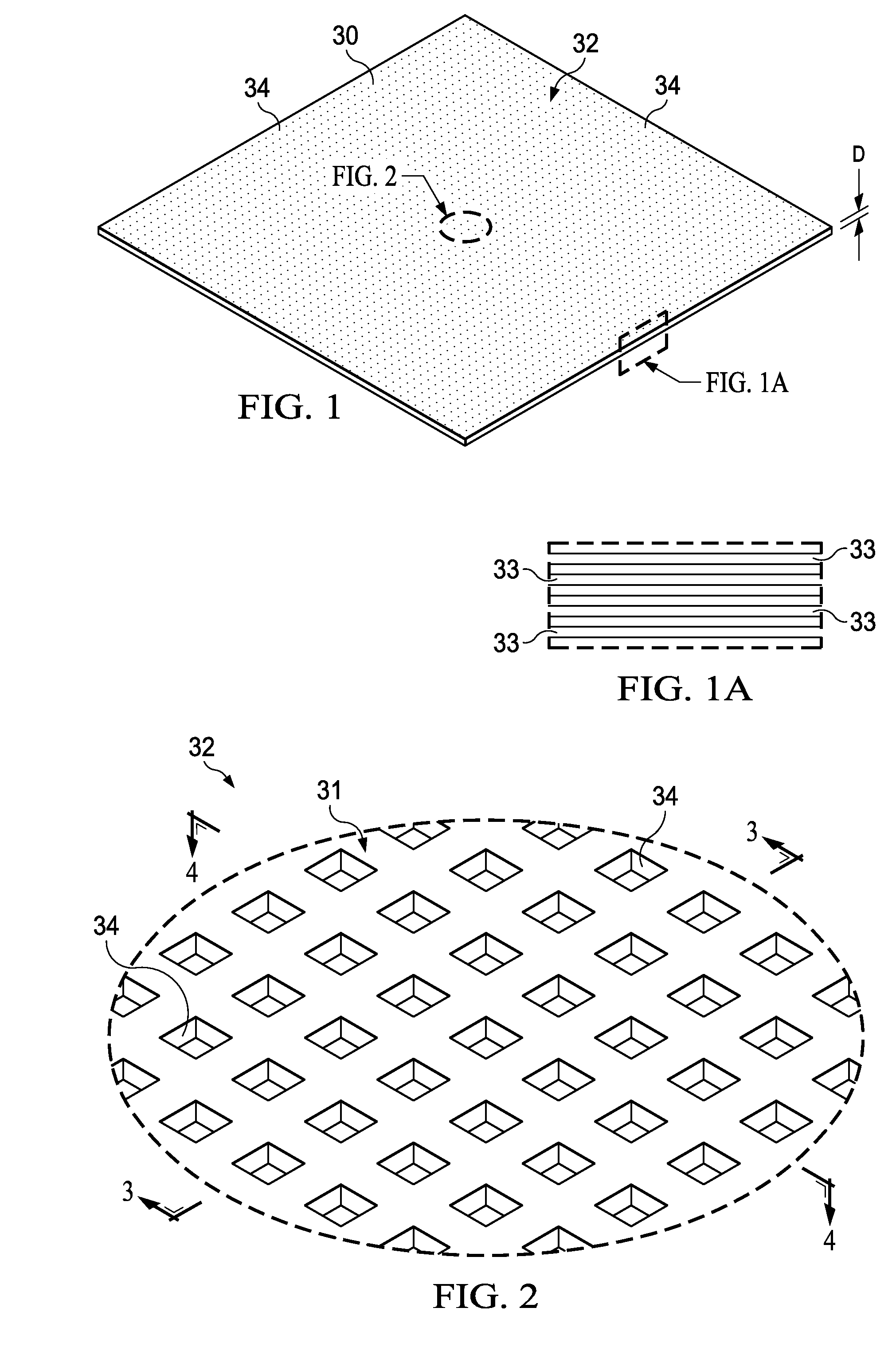
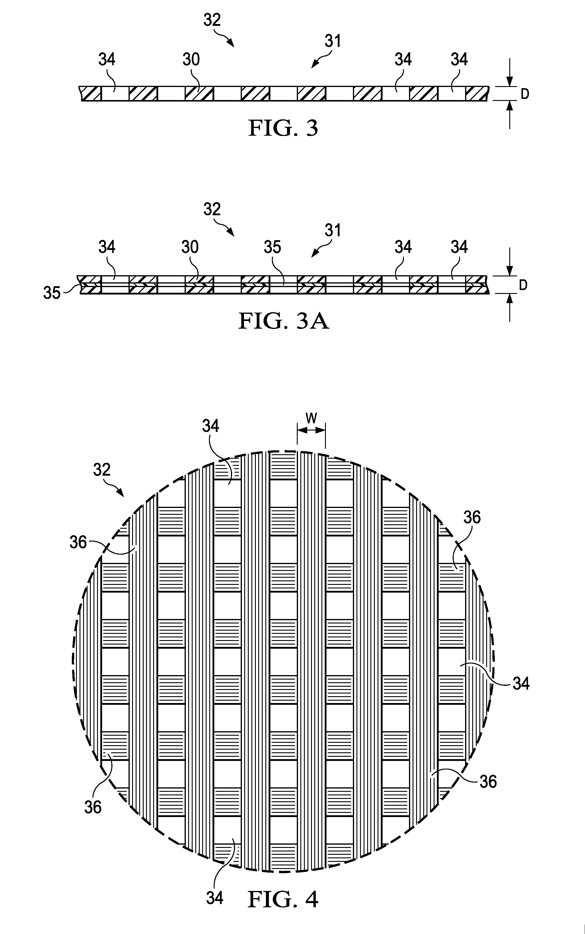
[0039]Referring to FIGS. 1-3, a composite laminate includes a plurality of perforations or holes 34 therein which are arranged in a pattern 32, sometimes hereinafter referred to as a hole pattern 32. In the illustrated embodiment, the holes 34 pass completely through the depth “D” of the laminate 30, however it may be possible to form the holes 34 only partially through the thickness of “D”. In the illustrated embodiment, the hole pattern 32 is a regular pattern in which the holes 34 arranged in a matrix, however in other embodiments the hole pattern 32 may be irregular, depending upon the application. The laminate 30 comprises a plurality of plies 33 (FIG. 1A) of a fiber reinforced resin such as, without limitation, carbon fiber epoxy or other thermoset, or a fiber reinforced thermoplastic.

[0040]In some embodiments, as shown in FIG. 3A, one or more layers 35 of material may be embedded between the plies 33 in order to tailor the laminate 30 to particular applications. The embedded ...


PUM

PropertyMeasurementUnit
widthsaaaaaaaaaa
sizeaaaaaaaaaa
widthaaaaaaaaaa

Abstract

A composite laminate has a pattern of holes therein. The holes are formed by laying down plies of unidirectional pre-preg material having varying fiber orientations. The tows are spaced apart and located to form holes through the laminate.

Description

BACKGROUND INFORMATION[0001]1. Field[0002]The present disclosure generally relates to processes for fabricating composite laminates, and deals more particularly with a method of producing hole patterns in such laminates using controlled fiber placement, and to laminates having hole patterns produced thereby.[0003]2. Background[0004]It is sometimes necessary to form a large number of holes or perforations in a composite structure. For example, acoustically treated structures may employ an acoustic panel having an outer composite laminate facesheet provided with thousands of perforations. The facesheet perforations cooperate with a cellular panel core to attenuate sound. Aircraft wing skins may also include composite laminate facesheets that are perforated in order to alter the airflow over the wing.[0005]Current techniques for forming a large number of perforations or holes in a composite laminate can be time consuming, labor intensive and expensive. In one technique, tooling referre...

Claims


Application Information

Patent Timeline
Patent Type & Authority Applications(United States)
IPC IPC(8): B32B3/12
CPCB32B3/12B32B5/12B32B5/26B32B3/02B32B3/266B32B2260/046B32B2262/106B32B2605/00B29C70/386B29C70/224B32B2305/024B32B2307/102B32B5/022B32B5/024B32B2260/023Y10T428/24074B32B5/28B29C70/30
Inventor BUTLER, GEOFFREY ALLENJOHNSON, BRICE A.HUGHES, JESSICA R.LAN, JUSTIN HONSHUNE
Owner THE BOEING CO
Why Eureka
Try Eureka