Micromechanical Structure for Receiving and/or Generating Acoustic Signals, Method for Producing a Micromechnical Structure, and Use of a Micromechanical Structure

a micromechanical and acoustic signal technology, applied in the direction of electrical transducers, semiconductor devices, electrical apparatus, etc., can solve the problems of inability to incouple or outcouple acoustic signals on the top or bottom side, and reduce so as to improve the sensitivity of the assemblage, and improve the acoustic properties of the micromechanical structur

Inactive Publication Date: 2010-01-07
ROBERT BOSCH GMBH
View PDF4 Cites 23 Cited by
  • Summary
  • Abstract
  • Description
  • Claims
  • Application Information

AI Technical Summary

Benefits of technology

[0005]The micromechanical structure according to the present invention for receiving and / or generating acoustic signals in a medium at least partially surrounding the structure, and the method for producing a micromechanical structure and the use of a micromechanical structure according to the present invention have the advantage that with simple means, an improvement in the acoustic properties of the micromechanical structure is possible, and the micromechanical structure is nevertheless producible by way of a comparatively simple and robust production method. The micromechanical structure according to the present invention exhibits great mechanical stability because of the embedding of the diaphragm (buried diaphragm) between the first and the second counterelement.
[0006]It is particularly preferred that a first cavity be configured between the first counterelement and the diaphragm and that a second cavity be configured between the diaphragm and the second counterelement, and that the first counterelement have a mass several times greater as compared with the diaphragm and / or that the second counterelement have a mass several times greater as compared with the diaphragm. This makes possible, with simple means, a further improvement in the acoustic properties of the micromechanical structure.
[0008]It is further preferred that the first and / or second counterelement be provided in a manner produced essentially from semiconductor material, and that the diaphragm encompass semiconductor material, and that the first counterelement have a first electrode, the second counterelement have a second electrode, and the diaphragm have a third electrode. It is thereby advantageously possible for the electrical properties of the micromechanical structure to be optimized to the extent that differential evaluation of the change in capacitance between the electrodes is enabled.
[0009]A further subject of the present invention is a method for producing a micromechanical structure according to the present invention, such that for production of the second cavity, a first sacrificial layer either is applied in patterned fashion onto a raw substrate or is introduced in patterned fashion into the raw substrate, and a first precursor structure is obtained; that then, for production of the diaphragm, at least one first diaphragm layer is applied onto the first precursor structure; that then, for production of the first cavity, a second sacrificial layer is applied; and that then, for production of the first counterelement, an epitaxic layer is applied, the first and second openings then being introduced into the counterelements and the first and the second sacrificial layer being removed in order to constitute the first and the second cavity. This makes it possible, in particularly advantageous fashion, to produce the micromechanical structure according to the present invention by way of a relatively robust and comparatively inexpensive production process.

Problems solved by technology

A disadvantage here is that because of the substrate being closed off toward the bottom, no top- or bottom-side incoupling or outcoupling of acoustic signals is possible.
It is additionally disadvantageous that the sensitivity of the assemblage is thereby reduced.

Method used


Image

  • Micromechanical Structure for Receiving and/or Generating Acoustic Signals, Method for Producing a Micromechnical Structure, and Use of a Micromechanical Structure
  • Micromechanical Structure for Receiving and/or Generating Acoustic Signals, Method for Producing a Micromechnical Structure, and Use of a Micromechanical Structure
  • Micromechanical Structure for Receiving and/or Generating Acoustic Signals, Method for Producing a Micromechnical Structure, and Use of a Micromechanical Structure

Examples


Embodiment Construction

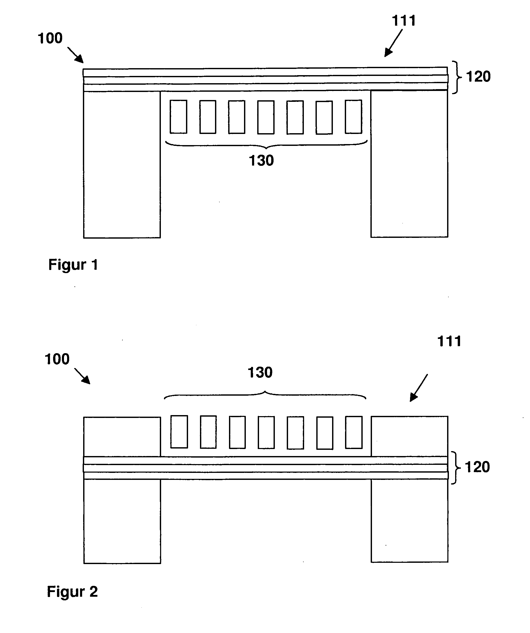
[0014]FIGS. 1 and 2 depict two micromechanical structures 100 known according to the existing art, which each have a diaphragm 120 and a grid-shaped counterelectrode 130. In one case, diaphragm 120 constitutes the surface of the micromechanical structure on a first side 111 (FIG. 1), and in the other case diaphragm 120 is provided in buried fashion, i.e. counterelectrode 130 of micromechanical structure 100 constitutes the surface of micromechanical structure 100 on first side 111 (FIG. 2).

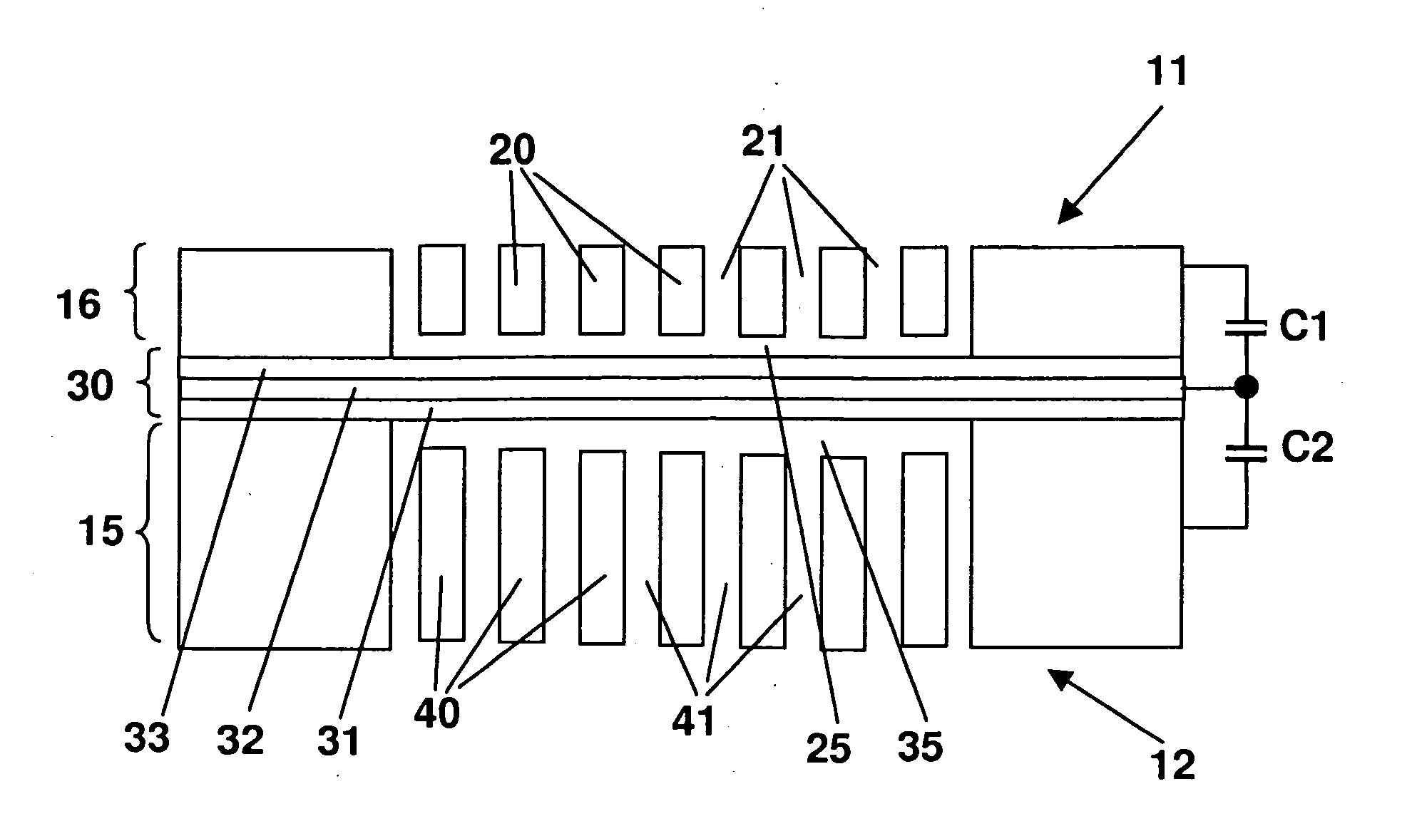
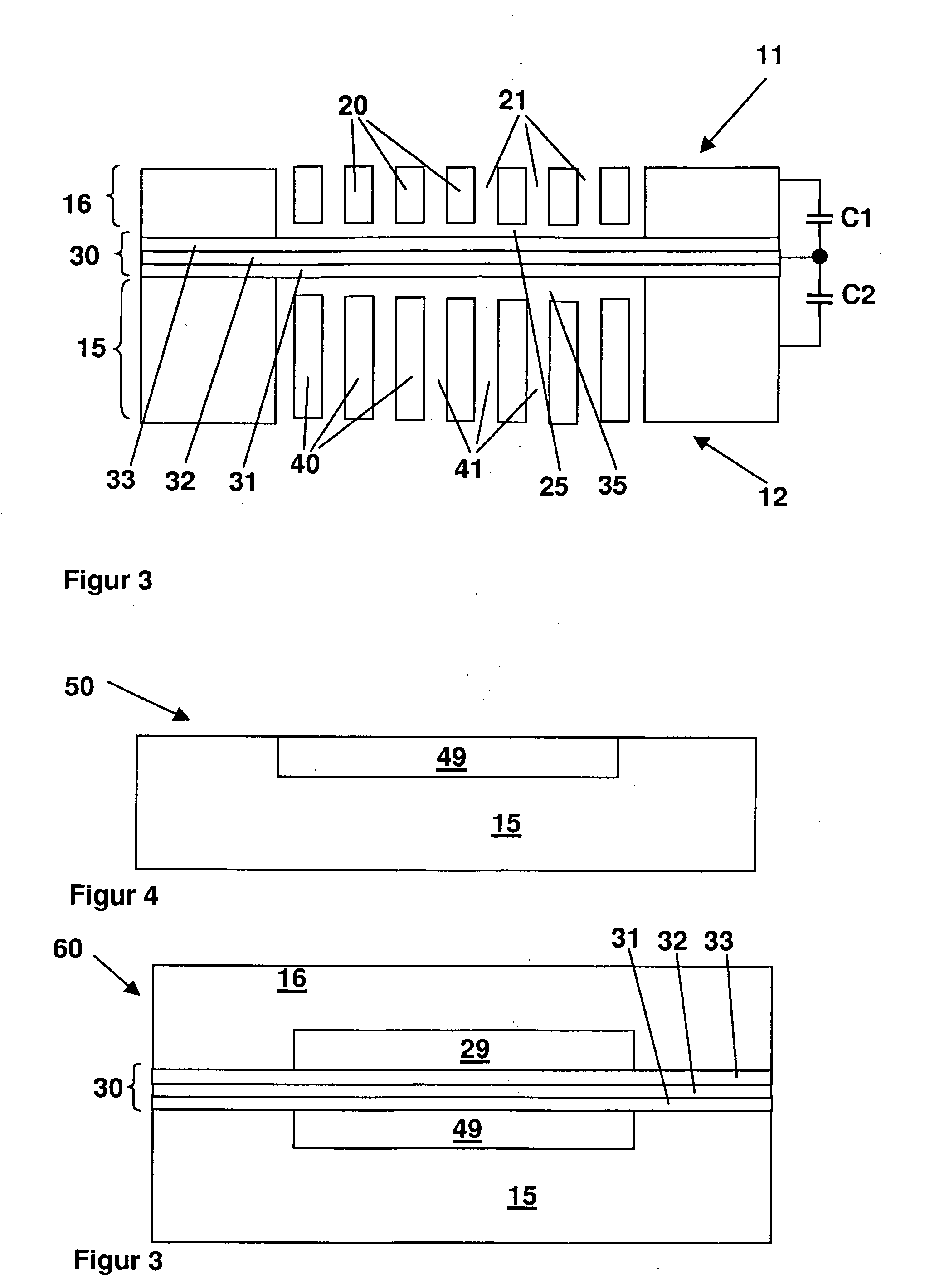
[0015]FIG. 3 depicts a micromechanical structure 10 according to the present invention. FIG. 4 depicts a first precursor structure 50, and FIG. 5 a second precursor structure 60. FIGS. 3 to 5 are hereinafter described together. Micromechanical structure 10 according to the present invention has a first counterelement 20, a diaphragm 30, and a second counterelement 40. First counterelement 20 has first openings 21, and second counterelement 40 has second openings 41. According to the present invent...


PUM


Abstract

A micromechanical structure and a method for producing a micromechanical structure are provided, the micromechanical structure being configured for receiving and / or generating acoustic signals in a medium at least partially surrounding the structure. The structure includes a first counterelement that has first openings and essentially forms a first side of the structure, a second counterelement that has second openings and essentially forms a second side of the structure, and an essentially closed diaphragm disposed between the first counterelement and the second counterelement.

Description

BACKGROUND OF THE INVENTION[0001]1. Field of the Invention[0002]The present invention relates to a micromechanical structure for receiving and / or generating acoustic signals in a medium at least partially surrounding the structure.[0003]2. Description of Related Art[0004]U.S. Patent Application 2002 / 0151100 A1 discloses a monolithically integrated pressure sensor having a microphone cavity, a backplate being disposed above an acoustic diaphragm located in a middle plane, the diaphragm being disposed above a cavity, the cavity being closed off toward the bottom by a substrate. A disadvantage here is that because of the substrate being closed off toward the bottom, no top- or bottom-side incoupling or outcoupling of acoustic signals is possible. It is additionally disadvantageous that the sensitivity of the assemblage is thereby reduced.BRIEF SUMMARY OF THE INVENTION[0005]The micromechanical structure according to the present invention for receiving and / or generating acoustic signals ...

Claims


Application Information

Patent Timeline
Patent Type & Authority Applications(United States)
IPC IPC(8): H04R19/00
CPCH04R19/005
Inventor SCHLOSSER, ROMANWEISS, STEFANFISCHER, FRANKSCHELLING, CHRISTOPH
Owner ROBERT BOSCH GMBH
Why Eureka
Try Eureka