Spark ignition internal combustion engine

a technology of internal combustion engine and spark ignition, which is applied in the direction of machines/engines, electrical control, applications, etc., can solve the problem that the air-fuel mixture within the cylinder cannot always be homogeneous

Inactive Publication Date: 2005-07-21
TOYOTA JIDOSHA KK
View PDF3 Cites 100 Cited by
  • Summary
  • Abstract
  • Description
  • Claims
  • Application Information

AI Technical Summary

Benefits of technology

[0007] The present invention has been made to solve the above problems. It is an object of the present invention to provide a spark ignition internal combustion engine that is capable of rendering the air-fuel mixture within the cylinder more homogeneous than in a case where the port injection technique is solely used.

Problems solved by technology

Therefore, if the port injection technique is solely used, the air-fuel mixture within the cylinder cannot always be rendered homogeneous.

Method used


Image

  • Spark ignition internal combustion engine
  • Spark ignition internal combustion engine
  • Spark ignition internal combustion engine

Examples


first embodiment

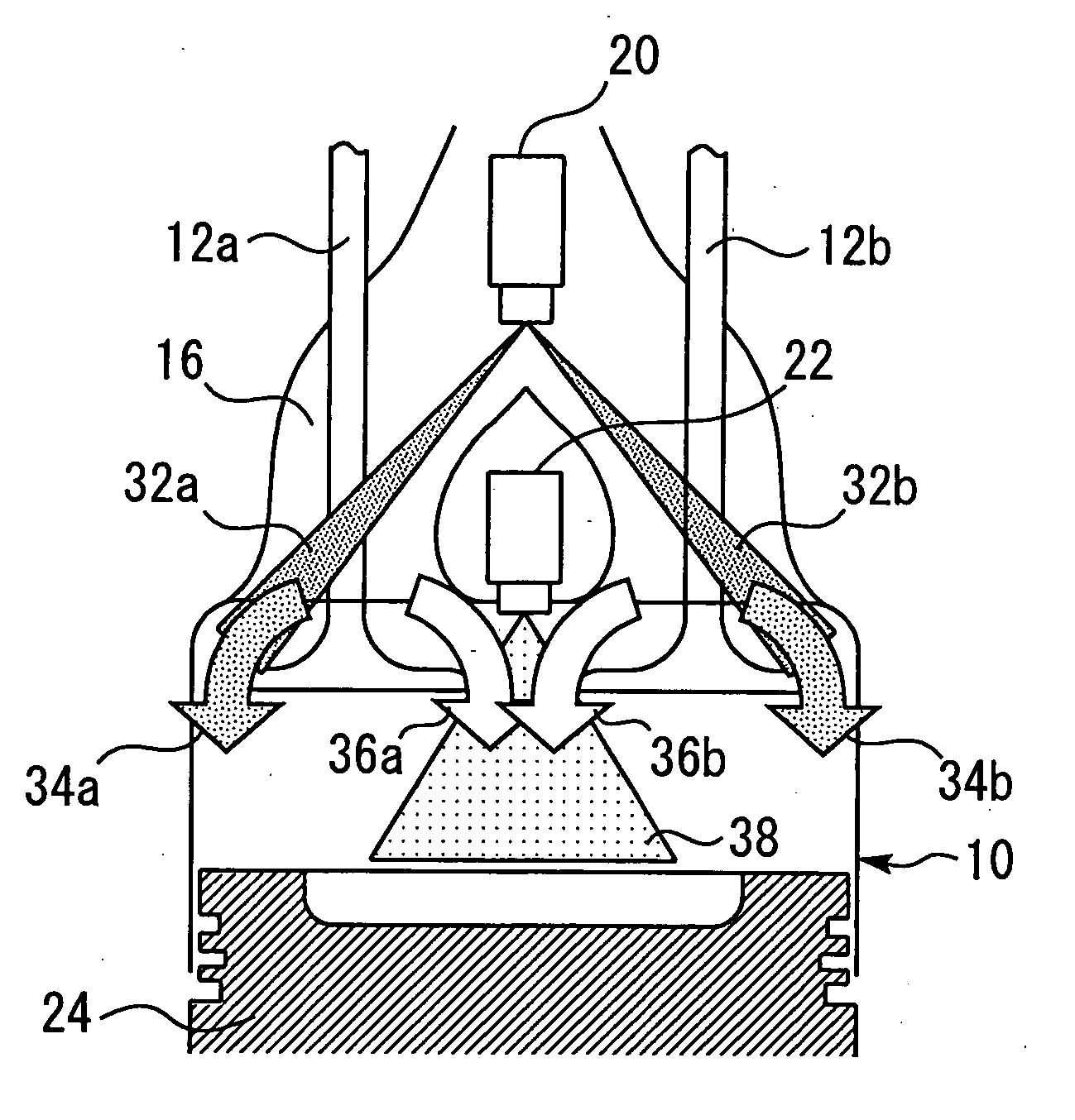
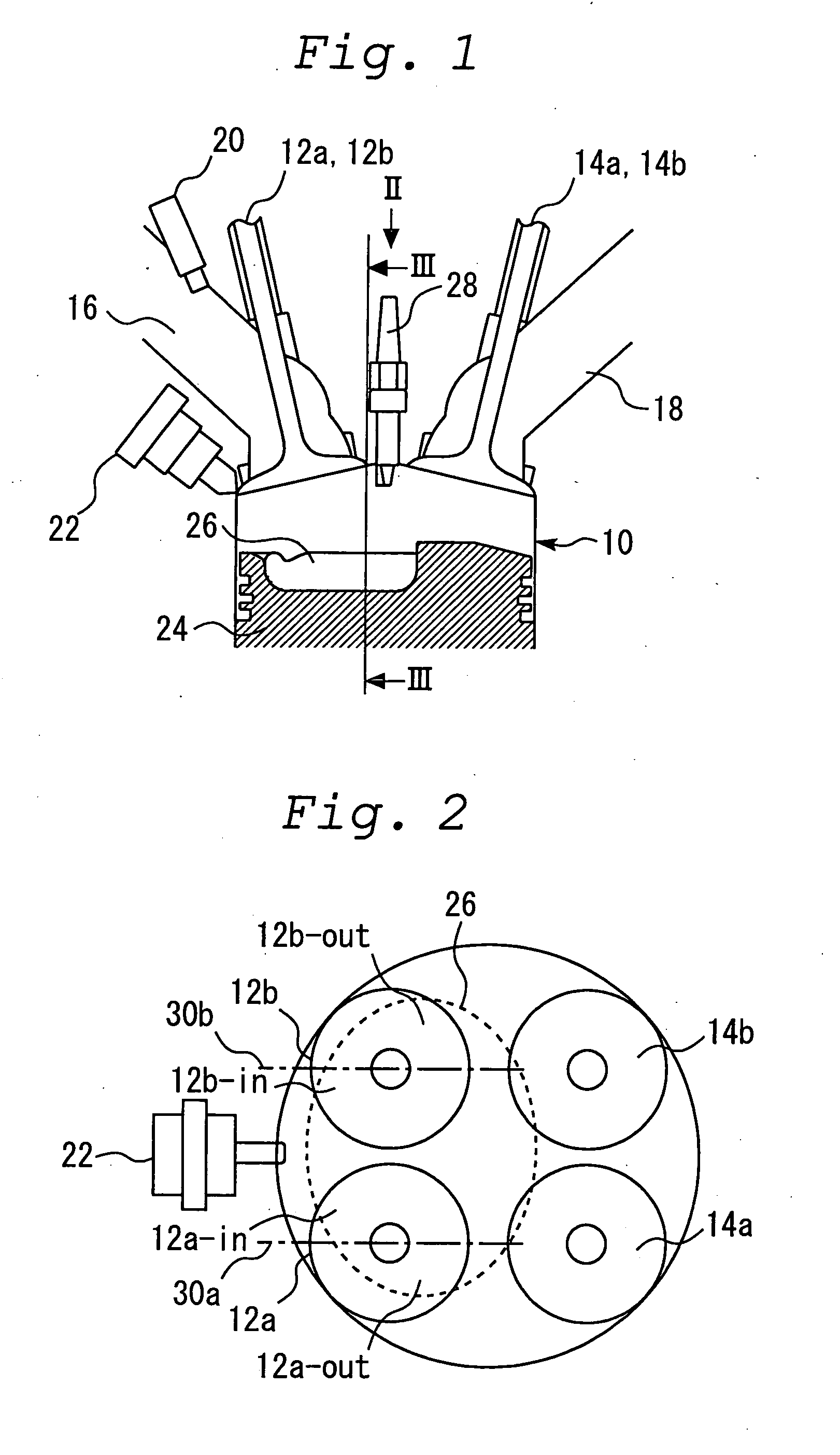
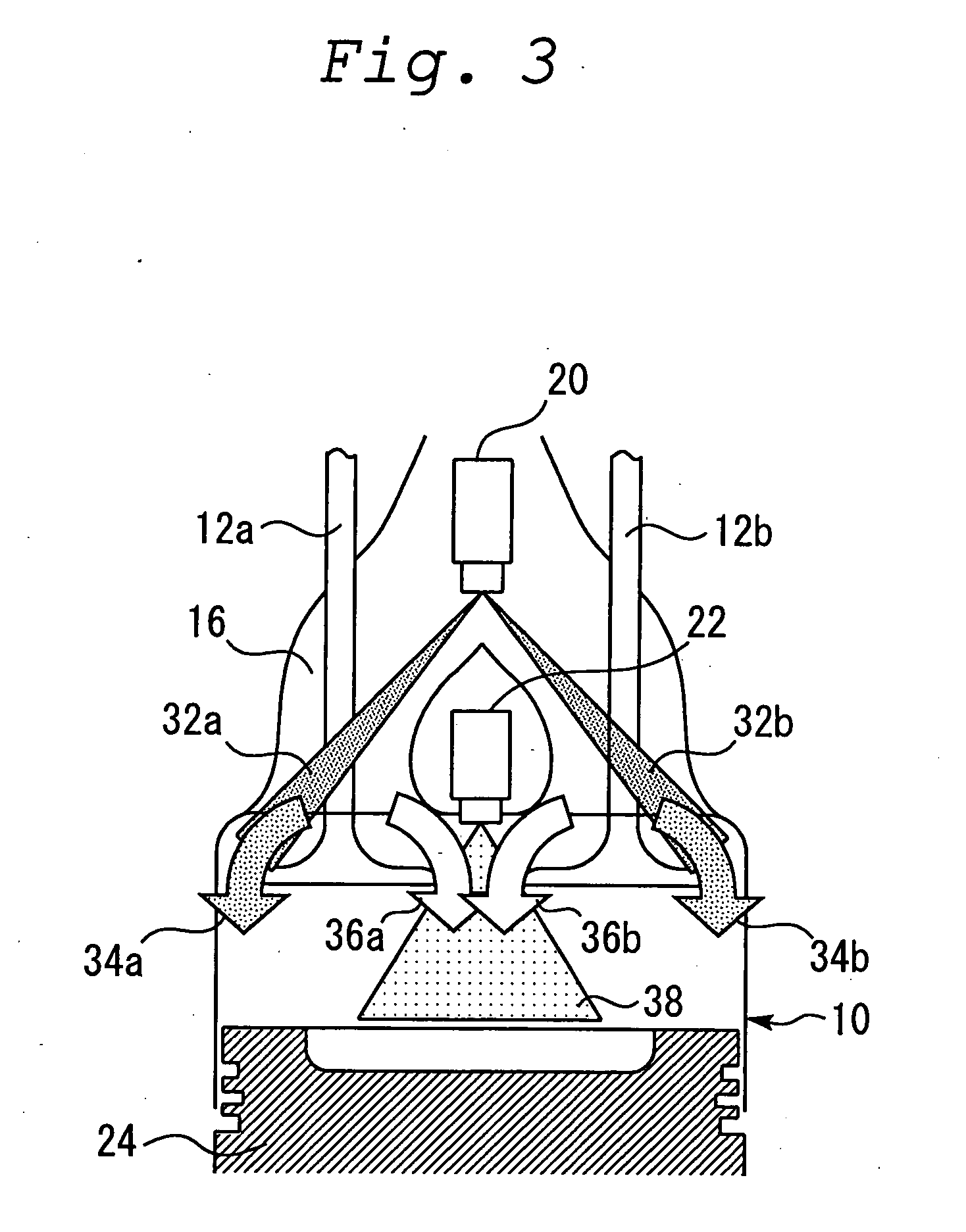
[0023]FIG. 1 illustrates the configuration of a first embodiment of the present invention. The system shown in FIG. 1 is equipped with an internal combustion engine 10. The internal combustion engine 10 has a plurality of cylinders. However, FIG. 1 merely shows a cross section of one of the cylinders. Each cylinder of the internal combustion engine 10 has two intake valves 12a and 12b and two exhaust valves 14a and 14b. The internal combustion engine 10 communicates with an intake port 16 and an exhaust port 18. The intake port 16 communicates with the two intake valves 12a and 12b. The exhaust port 18 communicates with the two exhaust valves 14a and 14b.

[0024] The intake port 16 has an injector for providing internal fuel injection, that is, a port fuel injector 20 for providing port injection. The internal combustion engine 10 also has an injector for injecting fuel into a cylinder, that is, an intra-cylinder fuel injector 22 for providing intra-cylinder injection. Further, the i...

second embodiment

[0038] A second embodiment of the present invention will now be described with reference to FIGS. 4 through 6. The second embodiment of the internal combustion engine 10 is configured the same as the first embodiment except that intake valves 12a and 12b are equipped with partitioning boards 40a and 40b, respectively. The same elements as those used in the first embodiment will be described briefly or will not be described at all. The following explanation mainly deals with portions that are particular to the second embodiment.

[0039]FIG. 4 is a cross-sectional view illustrating major elements of the internal combustion engine 10 according to the present embodiment. This cross-sectional view is obtained when the major elements of the internal combustion engine 10 are viewed in the direction squarely facing the two intake valves 12a and 12b. As indicated in FIG. 4, the internal combustion engine 10 according to the present embodiment includes the partitioning boards 40a and 40b, whic...

third embodiment

[0045] A third embodiment of the present invention will now be described with reference to FIGS. 7 through 10. The same elements as those used in the first embodiment are assigned the same reference numerals and will be described briefly or will not be described at all.

[0046]FIG. 7 illustrates the configuration of the internal combustion engine 10 according to the third embodiment. FIG. 8 presents view VIII of FIG. 7 to illustrate major elements of the internal combustion engine 10 according to the present embodiment. As indicated in these figures, each cylinder of the internal combustion engine 10 according to the present embodiment has three intake valves 12a, 12b and 12c. Intake valves 12a, 12b, and 12c are left-right symmetrically positioned as viewed from the port fuel injector 20 or intra-cylinder fuel injector 22. More specifically, intake valve 12c is positioned at the center while intake valves 12a and 12b are positioned on both ends.

[0047]FIG. 9 is a cross-sectional view...


PUM


Abstract

Each cylinder is provided with an ignition plug, two intake valves, an intra-cylinder fuel injector, and a port fuel injector. When homogeneous combustion is demanded, the intra-cylinder fuel injector and port fuel injector inject fuel on the same engine cycle. The port fuel injector is installed so that the amount of fuel directed toward outer regions of the intake valves is larger than that of fuel directed toward inner regions of the intake valves, thereby causing only fresh air to flow to regions near the inner regions of the intake valves.

Description

BACKGROUND OF THE INVENTION [0001] 1. Field of the Invention [0002] The present invention relates to a spark ignition internal combustion engine, and more particularly to a spark ignition internal combustion engine that is equipped with a port fuel injector and an intra-cylinder fuel injector. [0003] 2. Background Art [0004] A conventionally known spark ignition internal combustion engine is disclosed, for instance, by Japanese Patent Laid-Open No. 293304 / 1995. This conventional spark ignition internal combustion engine comprises a port fuel injector for injecting fuel into an intake port of an internal combustion engine and an intra-cylinder fuel injector for directly injecting fuel into a cylinder of the internal combustion engine. During low-to-medium load operation, this conventional internal combustion engine invokes stratified combustion by supplying fuel according to an intra-cylinder injection technique. During high load operation, on the other hand, the conventional interna...

Claims


Application Information

Patent Timeline
Patent Type & Authority Applications(United States)
IPC IPC(8): F02M61/14F02B17/00F02B23/08F02B23/10F02B31/00F02B31/08F02B75/12F02D41/30F02D41/38F02F1/42F02M63/00F02M63/02F02M69/04F02M69/36
CPCF02B23/104F02B2075/125F02B2275/14F02B2275/16F02D41/3094F02D2041/389Y02T10/123F02M69/044F02M69/045F02M69/046Y02T10/125F02B17/00F02M63/0225Y02T10/12A01K61/10A01K61/80
Inventor ICHISE, MASAHARUTOMODA, TERUTOSHIOKADA, YOSHIHIRO
Owner TOYOTA JIDOSHA KK
Why Eureka
Try Eureka