Diaphragm valve with pivoting closure member

a technology of diaphragm valve and closure member, which is applied in the direction of valve operating means/releasing devices, functional valve types, transportation and packaging, etc., can solve problems such as pressure drop within the system, and achieve the effect of increasing the closure force and reducing the pressure loss of fluid flowing

Active Publication Date: 2005-07-21
VICTAULIC
View PDF20 Cites 10 Cited by
  • Summary
  • Abstract
  • Description
  • Claims
  • Application Information

AI Technical Summary

Benefits of technology

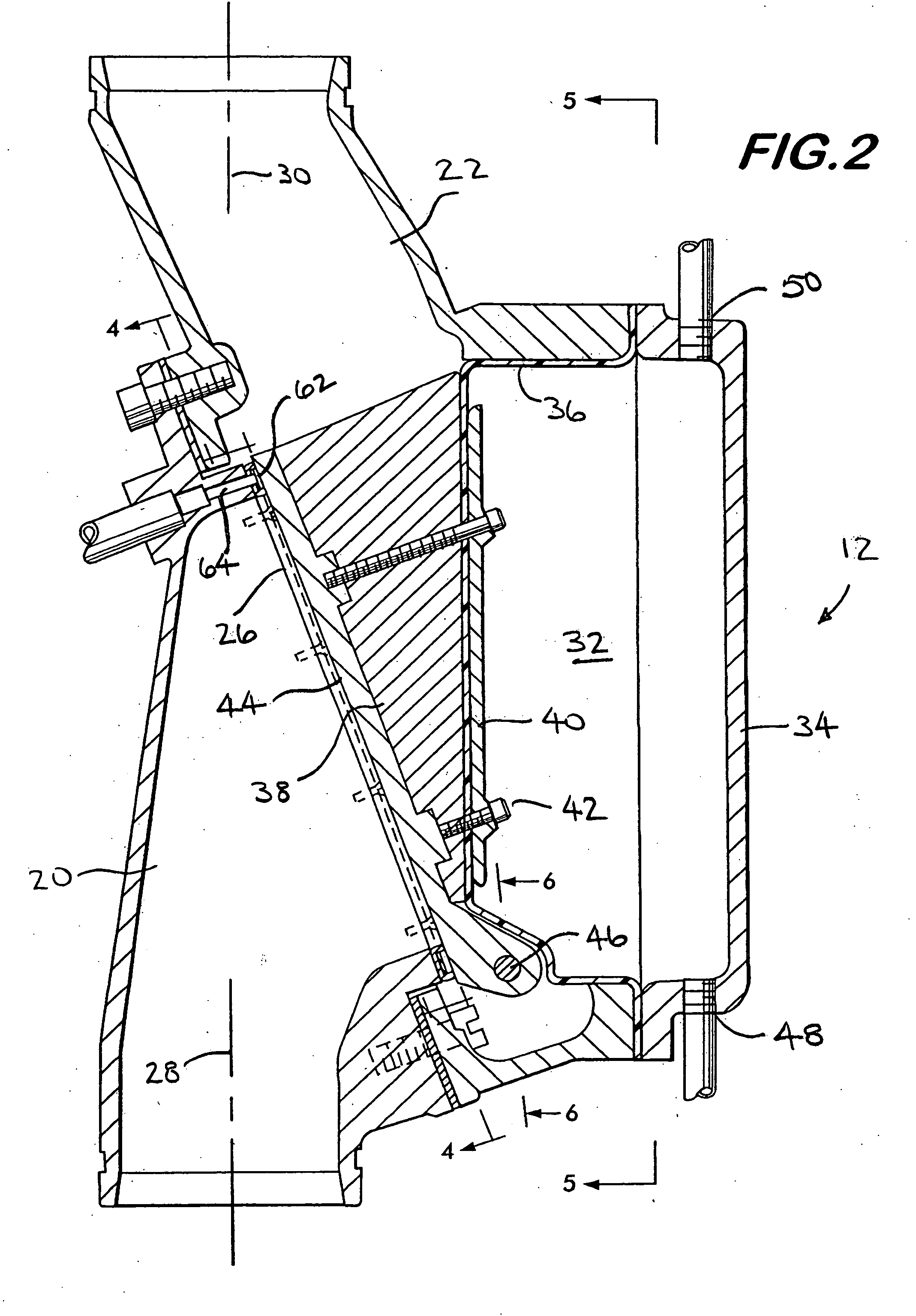
[0009] The valve seat may have a non-circular shape, preferably elliptical. The elliptical seat allows the inlet duct to be substantially coaxially aligned with the outlet duct, thereby reducing pressure loss of fluid flowing through the valve.
[0010] In one valve embodiment, the seat comprises a loop having an inner and an outer perimeter. A first projection extends along the inner perimeter, and a second projection extends along the outer perimeter. Both of the projections face the valve closure member for sealing engagement therewith upon pivoting of the valve closure member. The first and second projections are in spaced apart relation to each other and define a space between them. Preferably, this space is vented to the ambient to increase the closure force on the closure member. The loop may be comprised of a resilient, flexible material, or it may engage a resilient, flexible substrate mounted on the closure member to effect a seal between the seat and the closure member.
[0011] In another embodiment, the loop is mounted on the closure member and engages the seat. Again, the loop may be comprised of a resilient, flexible material or it may engage a resilient, flexible substrate comprising part of the seat to effect the valve closure member seal.

Problems solved by technology

Heat from the fire will cause sprinkler heads to open, allowing pressurized gas to escape from the piping network and result in a pressure drop within the system.

Method used


Image

  • Diaphragm valve with pivoting closure member
  • Diaphragm valve with pivoting closure member
  • Diaphragm valve with pivoting closure member

Examples


Embodiment Construction

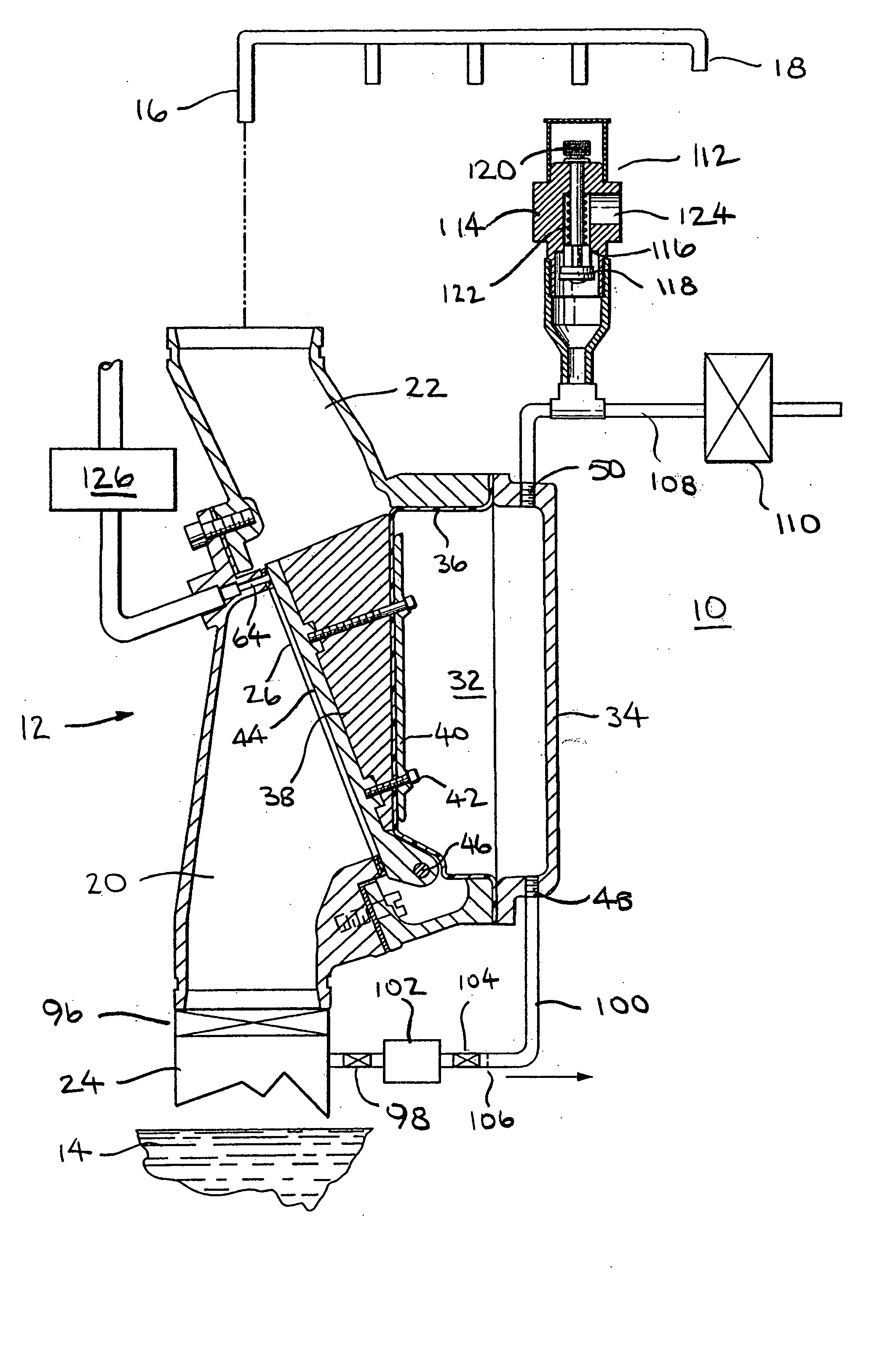
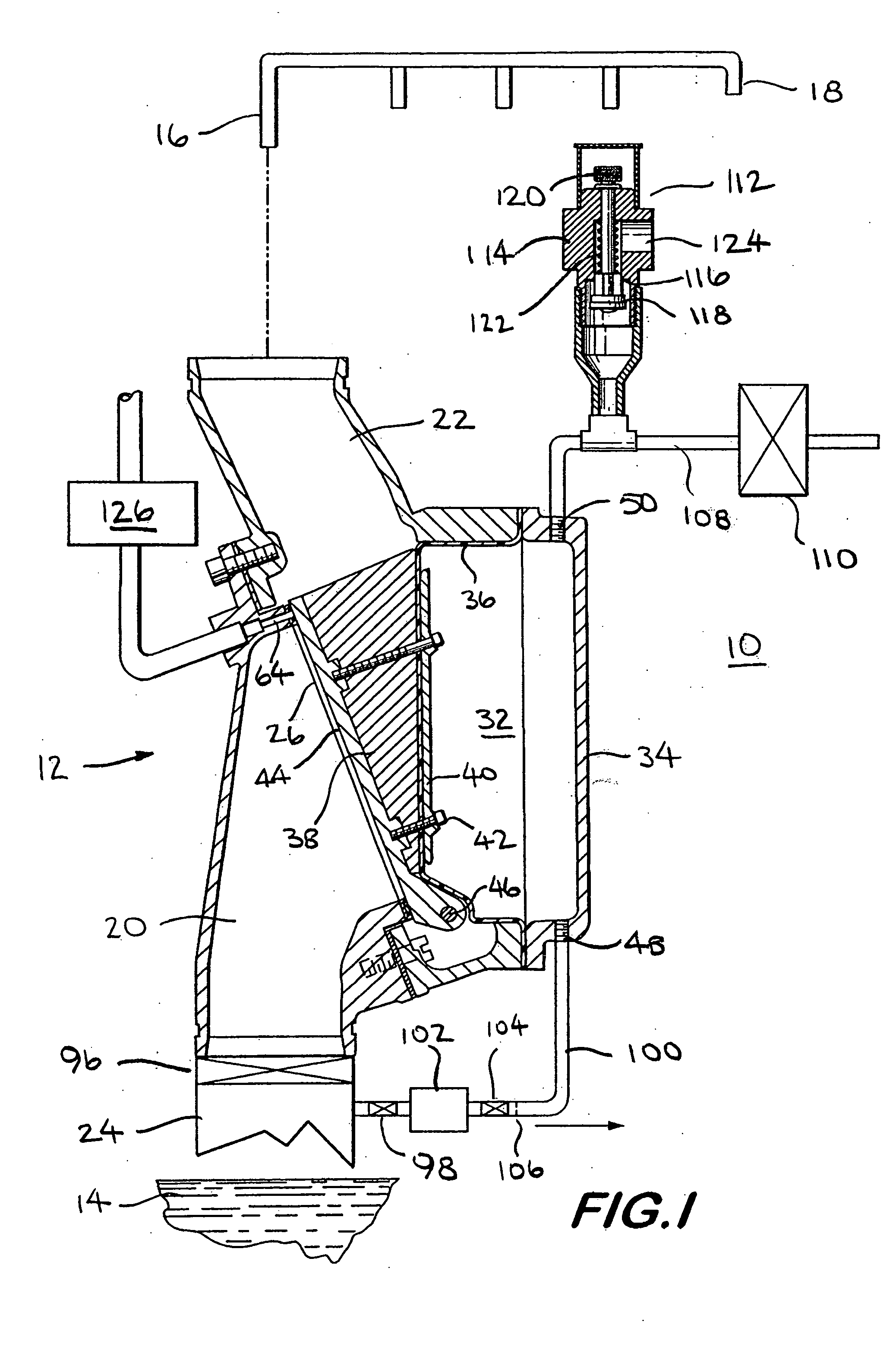
[0023]FIG. 1 shows a fire suppression sprinkler system 10 using a valve 12 according to the invention. Valve 12 functions to control the flow of a fire suppressing fluid, such as water, from a pressurized source 14 to a piping network 16. Piping network 16 is in fluid communication with sprinkler heads 18 that are distributed throughout the building or other structure in which the system 10 is installed. Upon a fire condition, valve 12 is opened, allowing water to flow from the source 14, through the piping network 16 to be discharged onto the fire by the sprinkler heads 18. A more detailed description of the valve, other system components, as well as system operation is provided below.

[0024] Valve 12 comprises an inlet duct 20 and an outlet duct 22. Inlet duct 20 is attachable to a main conduit 24 providing fluid communication between water source 14 and the valve, and the outlet duct 22 is attachable to the piping network 16 providing fluid communication between the valve 12 and ...


PUM


Abstract

A valve is disclosed having an inlet duct aligned with an outlet duct and an angularly oriented elliptical seat positioned between them. A pressure chamber faces the seat. A pivoting valve closure member is positioned between the pressure chamber and the seat. An asymmetrical rolling diaphragm is attached to the closure member and defines part of the pressure chamber. A seat engaging surface on the side of the closure member opposite the pressure chamber is sealingly engageable with the seat to close the valve. The valve closure member is pivoted into the closed positioned by pressurizing the pressure chamber. The valve remains closed against hydraulic pressure in the inlet duct. The valve is permitted to open by de-pressurizing the pressure chamber, allowing the closure member to pivot out of engagement with the seat. Fluid may then flow from the inlet duct to the outlet duct.

Description

FIELD OF THE INVENTION [0001] This invention relates to valves for control of fluid flow, and especially valves for use in fire suppression sprinkler systems. BACKGROUND OF THE INVENTION [0002] Automatic sprinkler systems for fire protection of buildings such as offices, warehouses, hotels, schools, apartments and the like are often required when there is a significant amount of combustible matter present in the building. The combustible matter may be found in the materials from which the building itself is constructed, as well as in the building contents, such as furnishings or stored goods. [0003] Of the various types of automatic sprinkler systems available, the pre-action systems find widespread use. Pre-action systems use an actuator which responds to a combination of signals from different detectors to trip a valve which allows water to flow from a pressurized water source to the sprinkler piping network. The water is then distributed onto the fire from the sprinkler heads. Si...

Claims


Application Information

Patent Timeline
Patent Type & Authority Applications(United States)
IPC IPC(8): A62C31/02A62C35/00A62C37/36F16K1/20F16K15/00F16K21/12F16K31/126F16K37/00
CPCA62C31/02F16K31/126F16K1/2007F16K1/2057F16K1/2014F16K1/2028Y10T137/7762
Inventor REILLY, WILLIAM J.BANIS, JOSEPH K.
Owner VICTAULIC
Why Eureka
Try Eureka