Multi-picture simultaneous display device, multi-picture simultaneous display method, video signal generator, and recording medium

a multi-picture simultaneous display and display device technology, applied in the direction of static indicating devices, identification means, instruments, etc., can solve the problems of limited indoor use of projectors for cinemas, disadvantageous brightness of expanded light, and tired viewers

Inactive Publication Date: 2005-07-21
SONY CORP
View PDF5 Cites 8 Cited by
  • Summary
  • Abstract
  • Description
  • Claims
  • Application Information

AI Technical Summary

Benefits of technology

[0014] It is an object of the present invention to provide a multi-picture simultaneous display device and a multi-picture simultaneous display method for simultaneously viewably displaying, without fragmentation as seen in a multi-window, a mixed picture generated from an N-screen (N>2) picture.

Problems solved by technology

However, the multi-window method separates a single screen into small pieces.
This makes a single area too small to view, thus causing the viewer to get tired.
The thus expanded light is disadvantageous in terms of brightness.
Therefore, the projector for the cinema is limited to indoor use.

Method used


Image

  • Multi-picture simultaneous display device, multi-picture simultaneous display method, video signal generator, and recording medium
  • Multi-picture simultaneous display device, multi-picture simultaneous display method, video signal generator, and recording medium
  • Multi-picture simultaneous display device, multi-picture simultaneous display method, video signal generator, and recording medium

Examples


Embodiment Construction

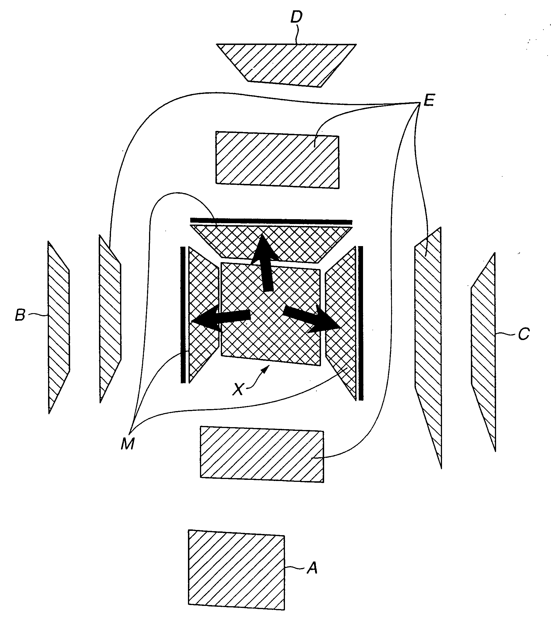
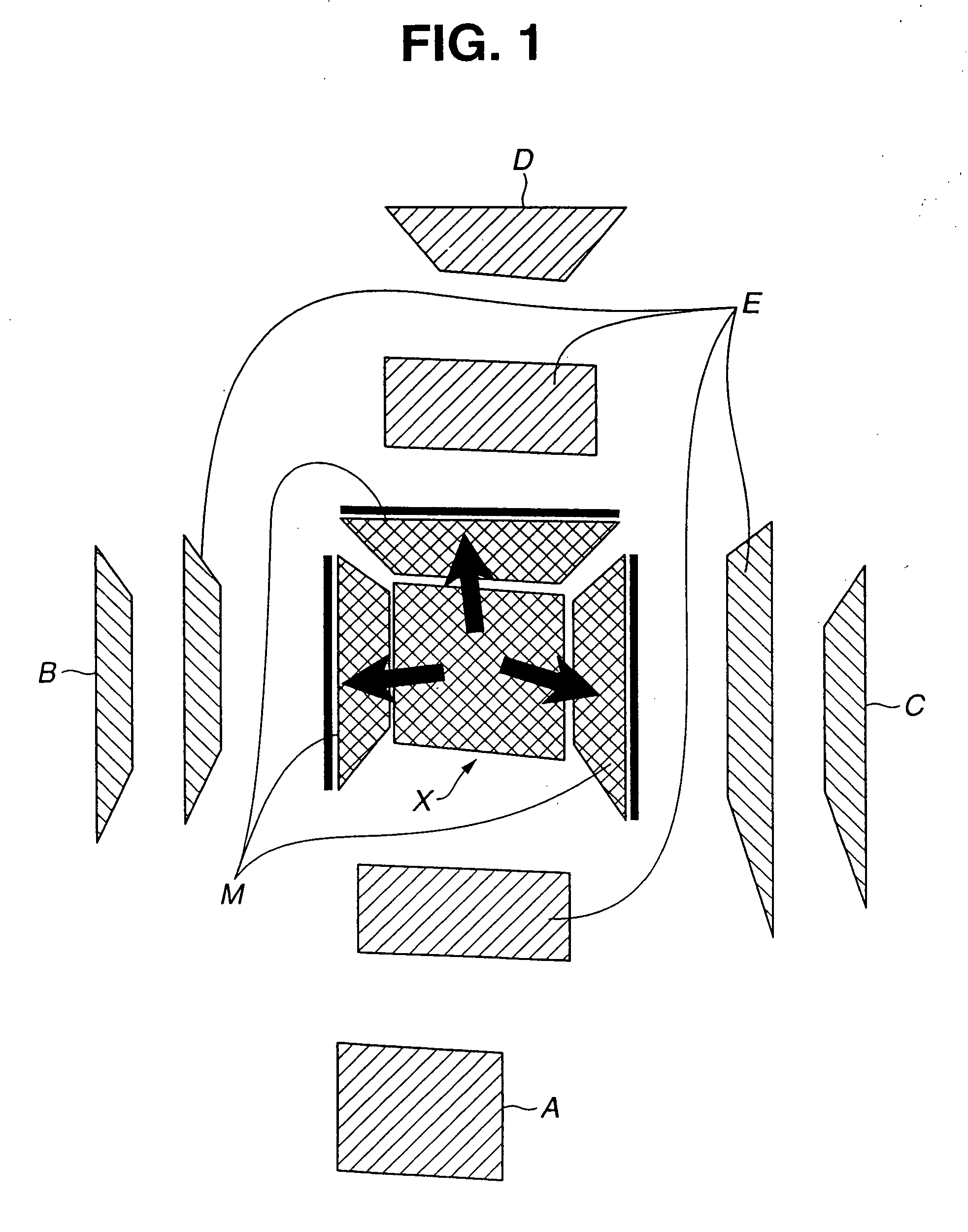
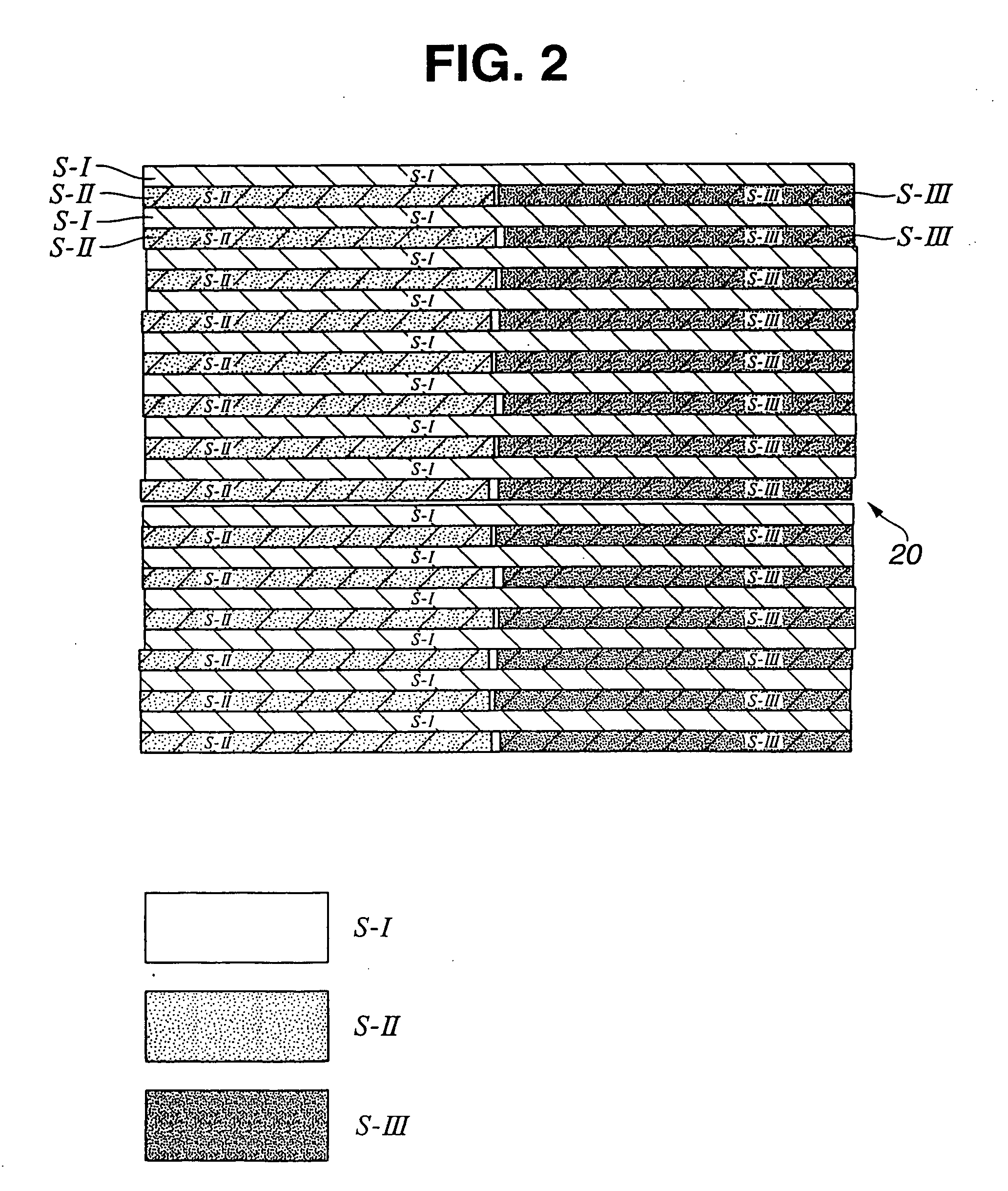
[0135] Described hereinafter is a mode for carrying out the invention, referring to attached drawings. At first, FIG. 1 shows a schematic constitution of one of the modes for carrying out the invention. FIG. 2 to FIG. 4 show a first mode for carrying out the invention. FIG. 2 shows a schematic of the example of the first mode for carrying out the invention. FIG. 3 shows a detailed drawing of a mixed picture copied on a display surface in FIG. 2. FIG. 4 shows a constitution viewed from an upper side.

[0136]FIG. 5 and FIG. 6 show a second mode for carrying out the invention, in which the display surface extends leftward and rightward, as compared with the display surface extending upward and downward according to the first mode for carrying out the invention. FIG. 7 shows a third mode for carrying out the invention, in which the display surface extends upward, downward, rightward, and leftward. Shown in FIG. 8 include elapsed time, display surface of the display device, direction of p...


PUM


Abstract

There are provided: a display surface (20) (mixed picture display part) for assigning a plurality of pieces of video information, respectively, to a plurality of a first divided area (S-I), a second divided area (S-II) and a third divided area (S-II), so as to display the plurality of the pieces of the video information on the display surface (20); a first picture separating mechanism disposed on the display surface (20) corresponding to the first divided area (S-I) of the plurality of the divided areas (S-I, S-II, S-Ill), and defining a predetermined polarizing direction; a second picture separating mechanism disposed on the display surface (20) corresponding to the second divided area (S-II) and the third divided area (S-III) of the plurality of the divided areas (S-I, S-II, S-III), and defining a predetermined polarizing direction different from the polarizing direction of the first picture separating mechanism; mirrors (optical means) (31, 32) disposed rightward and leftward relative to the display surface (20) in such a manner as to form respective predetermined angles relative to the display surface (20); and a third picture separating mechanism (40) defining a polarizing direction same as the polarizing direction of the first picture separating mechanism, and allowing a picture displayed on the display surface (20) and a picture displayed on the mirror (31, 32) to pass through the third separating mechanism (40) for a viewer to view the pictures.

Description

[0001] Multi-picture simultaneous display device, multi-picture simultaneous display method, video signal generator, and recording medium. TECHNICAL FIELD [0002] The present invention relates to a multi-picture simultaneous display device and a multi-picture simultaneous display method for displaying a plurality of screens on a single display surface. The present invention further relates to a video signal generator and a recording medium for displaying video information on the multi-picture display device. BACKGROUND TECHNIQUE [0003] With the recent information society, displaying more pieces of information is in great need. One known method is a multi-window for displaying a screen separated per section. A preferable example of the known method is a display terminal and the like of computer. Also in great need is a large screen such as a landscape of panoramic picture providing viewer with power. [0004] In view of the above consumer needs, the present inventor had already proposed...

Claims


Application Information

Patent Timeline
Patent Type & Authority Applications(United States)
IPC IPC(8): G06F3/14G09F9/302G09F9/40G09F19/12G09G3/00G09G3/20
CPCG06F3/1423G09F9/302G09F9/40G09G2300/026G09G3/002G09G3/003G09G3/20G09F19/12
Inventor SATO, SEIJISEKIZAWA, HIDEHIKO
Owner SONY CORP
Why Eureka
Try Eureka